
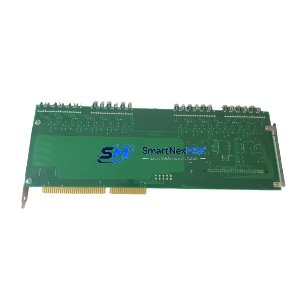
Siemens A1A461D85.00M Retrofit-Ready Control Board for SIMATIC S5 Control Systems
The Siemens A1A461D85.00M is a retrofit-ready PLC control board engineered for seamless integration into legacy SIMATIC S5 automation environments. As Siemens has progressively phased out the S5 product line in favor of the SIMATIC S7-300 and S7-400 platforms, sourcing reliable, tested replacements for the A1A461D85.00M has become a critical priority for plant engineers, maintenance teams, and system integrators managing aging control infrastructure. This unit is fully tested prior to shipment, backed by a 12-month warranty, and available from verified stock — making it an ideal solution for emergency breakdowns, planned overhauls, and phased migration projects alike.
Whether you are maintaining a SIMATIC S5-115U, S5-135U, or S5-155U rack-based system, the A1A461D85.00M control board slots into the existing backplane without requiring structural modifications to the control cabinet. Engineers replacing this board should verify the backplane slot assignment, confirm the module address settings via the onboard DIP switches, and cross-reference the existing CPU — such as the CPU 948 or CPU 928B — to ensure program memory compatibility before powering up the replacement unit.
Upgrade Compatibility Table
| Parameter | Details |
|---|---|
| SKU / Part Number | A1A461D85.00M |
| Brand | Siemens |
| Compatible Series | SIMATIC S5 (S5-115U, S5-135U, S5-155U) |
| Backplane Interface | S5 standard backplane bus (parallel bus architecture) |
| Installation Requirement | Direct slot replacement; verify DIP switch address settings |
| Communication Compatibility | SINEC H1, PROFIBUS-DP (via CP modules such as CP 5431) |
| Replacement Recommendation | Verify CPU type (CPU 948 / CPU 928B) and program block compatibility |
| Commissioning Notes | Re-load program from EPROM or PG 740/750 programmer; confirm I/O addressing |
| Warranty | 12 Months — covers functional defects under normal operating conditions |
| Pre-Shipment Testing | Full functional test performed before dispatch |
Retrofit Planning for Existing Automation Systems
A successful retrofit of the A1A461D85.00M begins well before the replacement board arrives on site. Maintenance engineers should start by auditing the full contents of the control cabinet: document the existing power supply module — typically a PS 951 or PS 955 — and confirm that its output capacity can support the replacement board alongside any co-installed I/O modules such as the SM 321 digital input module or SM 322 digital output module. Overloaded power rails are a common and preventable cause of post-retrofit instability.
Next, inspect the backplane or rack assembly — whether a UR1, UR2, or EU 183 expansion unit — for signs of corrosion, damaged bus connectors, or bent guide rails. A degraded backplane can cause intermittent communication faults that are easily misattributed to the replacement module itself. If the system uses a CP 5431 FMS/DP communication processor for PROFIBUS-DP connectivity, verify that the network parameters and station addresses are documented before removing the original board, as these settings may need to be re-entered during commissioning.
For systems that include an IM 308-C interface module managing distributed I/O over PROFIBUS, confirm that the DP master configuration stored in the CPU program is consistent with the physical I/O layout. Any mismatch between the configured and actual slave addresses will trigger a bus fault immediately upon startup. Similarly, if the control system interfaces with an OP 17 or TP 27 HMI panel, verify that the HMI communication driver and variable table remain intact after the board swap — HMI screen data is typically stored independently but communication link parameters may require re-validation.
Wiring termination at the front connector should be photographed and labeled before disconnection. S5 front connectors are keyed but terminal assignments vary by module type, and incorrect re-termination is a leading cause of post-replacement I/O errors. Where the original wiring documentation is unavailable, use a multimeter to trace and label each terminal before proceeding.
Downtime Control During System Migration
Minimizing production downtime during an S5 control board replacement requires a structured, pre-planned approach. Begin by scheduling the swap during a planned maintenance window and preparing a rollback plan — retain the original A1A461D85.00M board in a safe location until the replacement has been validated in production for at least one full operating cycle.
Before powering down, use a PG 740 or PG 750 programming device — or a modern PC-based STEP 5 programming environment — to perform a full program backup, including all OBs, FBs, FCs, and DB blocks. Store the backup on both the programming device and an external medium. If the CPU uses an EPROM memory card, retain the original card as a secondary backup source.
During the swap, work systematically: remove the front connector first, then release the module locking mechanism, and extract the board along the guide rails. Insert the A1A461D85.00M replacement, reconnect the front connector, and restore power in a controlled sequence — power supply first, then CPU, then I/O modules. Monitor the CPU diagnostic LEDs during startup: a steady RUN LED with no SF (system fault) indication confirms a clean initialization. If the SF LED illuminates, connect the programming device immediately and read the diagnostic buffer to identify the fault source before resuming production.
For systems where continuous process control is critical, consider staging a parallel test rack using a second UR2 rack populated with a tested CPU and the replacement A1A461D85.00M board. Load the backed-up program, simulate I/O signals, and validate logic execution offline before committing to the live system swap. This approach can reduce live commissioning time to under 30 minutes in most cases.
Retrofit Support FAQ
Q1: Is the A1A461D85.00M a direct drop-in replacement for the original Siemens board in my S5-135U system?
A: Yes, the A1A461D85.00M is designed for direct slot replacement within the SIMATIC S5-135U and compatible S5 racks. You should verify the DIP switch address configuration matches your original module settings and confirm that the backplane bus connectors are clean and undamaged before installation.
Q2: Will my existing STEP 5 program run without modification after replacing the board?
A: In most cases, yes — provided the replacement board is the same functional type and the CPU (e.g., CPU 948 or CPU 928B) and memory configuration remain unchanged. If the original program was stored on an EPROM card, re-insert it after installation. If stored in battery-backed RAM, restore from your PG backup. Always perform a full I/O check and logic test before returning the system to automatic mode.
Q3: What should I check regarding wiring and terminal connections during the replacement?
A: Photograph and label all front connector wiring before disconnection. Verify terminal assignments against the original wiring diagram or module data sheet. Pay particular attention to power supply terminals and any analog signal wiring, which is sensitive to incorrect termination. Re-torque all screw terminals to the specified value after reconnection.
Q4: What does the 12-month warranty cover, and is pre-shipment testing performed?
A: Every A1A461D85.00M unit undergoes full functional testing before dispatch to verify board-level operation. The 12-month warranty covers manufacturing defects and functional failures under normal operating conditions. It does not cover damage resulting from incorrect installation, overvoltage events, or physical mishandling. For warranty claims or technical support, contact [email protected] or call +86 18259474341.
© 2026 SMARTNEXMSK. All rights reserved.
Original Source: https://smartnexmsk.com
Contact: [email protected] | +86 18259474341



