
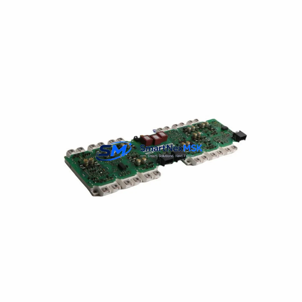
Siemens A5E00714561 FS300R12KE3 Retrofit-Ready IGBT Gate Driver for SINAMICS & MASTERDRIVES Control Systems
The Siemens A5E00714561, paired with the FS300R12KE3 IGBT module, is a precision gate driver board engineered for high-power drive applications across the SINAMICS and MASTERDRIVES platform families. As legacy drive systems reach end-of-life and OEM support windows close, this component has become a critical retrofit solution for plant engineers managing aging control infrastructure. Whether you are replacing a failed unit in a SINAMICS G150 cabinet drive, upgrading a MASTERDRIVES MC inverter, or restoring a production line after an unplanned shutdown, the A5E00714561 provides a verified drop-in replacement path with minimal re-engineering effort.
This gate driver board interfaces directly with the FS300R12KE3 IGBT power module — a 1200V / 300A six-pack module commonly found in medium-voltage drive cabinets. The board manages gate pulse distribution, desaturation protection, and fault feedback signaling, making it a safety-critical component in the power conversion chain. Procurement teams and maintenance engineers should confirm the exact revision suffix of the A5E00714561 against the installed drive’s BOM before ordering, as minor hardware revisions may affect gate resistor values and interlock timing.
Upgrade Compatibility Table
| Parameter | Details |
|---|---|
| Compatible Drive Families | SINAMICS G150, SINAMICS S150, MASTERDRIVES MC, MASTERDRIVES VC |
| Matched IGBT Module | FS300R12KE3 (1200V / 300A, Six-Pack) |
| Interface / Backplane | Direct plug-in to Siemens power stack; connector pitch compatible with standard SINAMICS power section |
| Communication Compatibility | PROFIBUS DP, PROFINET IO (via CU320-2 or CU310-2 Control Unit) |
| Installation Requirement | Torque-controlled fastening; thermal interface pad replacement recommended during retrofit |
| Replacement Recommendation | Replace gate driver and IGBT module as a matched pair; do not reuse aged IGBT with new driver board |
| Commissioning Focus | Verify DC bus pre-charge sequence, gate pulse timing via STARTER / SINAMICS Startdrive, and fault log clearance |
| Warranty | 12-Month Warranty — covers manufacturing defects and functional failure under normal operating conditions |
Retrofit Planning for Existing Automation Systems
A successful retrofit of the A5E00714561 gate driver board requires a structured approach that accounts for the full drive system context — not just the failed component. Before removing the defective board, engineers should document the existing fault codes stored in the CU320-2 Control Unit or legacy CU240E-2 control module, as these logs provide critical diagnostic context for root-cause analysis and help prevent repeat failures after the replacement is installed.
Power supply integrity is the first checkpoint. The 24VDC SITOP PSU300M or equivalent regulated supply feeding the control section must be verified for voltage stability under load. A marginal power supply is a common upstream cause of gate driver failure and must be ruled out before commissioning the replacement board. Similarly, the DC bus capacitor bank — typically housed in the Siemens SINAMICS power module PM250 or PM260 — should be inspected for capacitance drift if the drive has been in service for more than five years.
Terminal wiring and connector integrity are equally important. The fiber optic links between the CU320-2 and the power section, as well as the 37-pin sub-D interface on the Control Interface Module (CIM), should be cleaned and re-seated. Corroded or intermittently connected fiber optic cables are a frequent source of nuisance faults that can be misdiagnosed as gate driver failures. If the system uses a Siemens SMC30 Sensor Module Cabinet-Mounted for encoder feedback, verify that the encoder signal is clean and within specification before restarting the drive.
For systems that include a Siemens OP177B operator panel or TP900 Comfort Panel HMI, confirm that the HMI project version is compatible with the firmware version on the replacement control unit. In some MASTERDRIVES MC retrofit scenarios, the HMI screen layouts reference drive parameters that have been renumbered in newer firmware releases, requiring a parameter mapping review before the system is returned to automatic mode.
I/O expansion cards such as the Siemens TM31 Terminal Module or TM15 Terminal Module should be re-addressed after any control unit replacement. Module addressing is stored in the drive project file on the CF card; if the CF card is being replaced alongside the gate driver board, the full drive parameterization must be reloaded via STARTER or SINAMICS Startdrive and verified against the as-built parameter list. Communication links to the plant DCS — whether via PROFIBUS DP using a CBP2 Communications Board or via PROFINET IO — must be re-established and tested with the PLC program in manual mode before switching to automatic production control.
Downtime Control During System Migration
Minimizing production downtime during a gate driver replacement requires pre-staging all replacement components before the maintenance window begins. The A5E00714561 board, the matched FS300R12KE3 IGBT module, thermal interface pads, and any associated fiber optic cables should be on-site and verified against the drive’s parts list before the line is shut down. A pre-tested spare assembly — where the gate driver has been bench-verified for gate pulse output using a drive simulator or equivalent test rig — reduces the risk of discovering a secondary fault during the live replacement window.
The original PLC program logic should be backed up from the S7-300 or S7-400 CPU — or from the S7-1500 if the control system has already been partially modernized — before any power is removed from the drive cabinet. Drive parameters should be exported from the CU320-2 CF card and stored on a secure engineering workstation. This backup protects against accidental parameter loss during the replacement and provides the baseline for post-commissioning verification.
During the physical replacement, the DC bus must be fully discharged and verified with a calibrated voltmeter before any work begins on the power section. After the new gate driver board is installed and the IGBT module is torqued to specification, the drive should be powered up in a controlled sequence: control power first, then DC bus pre-charge, then a no-load test run at reduced speed setpoint. Fault codes should be cleared only after the root cause has been confirmed and corrected. The drive should be returned to full production speed only after a stable no-fault run of at least 30 minutes under load.
Retrofit Support FAQ
Q: Is the A5E00714561 a direct drop-in replacement for all SINAMICS and MASTERDRIVES variants?
A: The A5E00714561 is compatible with drive variants that use the FS300R12KE3 IGBT module in the power section. Compatibility should be confirmed against the drive’s type plate and BOM. Minor hardware revision differences (e.g., -AA0 vs. -AB0 suffix) may affect gate resistor values; contact our technical team with your drive’s full type designation for confirmation before ordering.
Q: What commissioning steps are required after installing the replacement board?
A: After physical installation, reload drive parameters from the CF card backup, clear all stored fault codes, and perform a no-load test run using STARTER or SINAMICS Startdrive. Verify gate pulse timing, check the DC bus pre-charge sequence, and confirm all I/O signals and communication links are active before returning the drive to automatic mode.
Q: How is the unit tested before shipment?
A: Every A5E00714561 unit is functionally tested prior to dispatch. Testing includes gate pulse output verification, desaturation protection response, and fault feedback signal integrity. A test report is available upon request. All units are shipped with ESD-protective packaging and include a 12-month warranty covering manufacturing defects and functional failure under normal operating conditions.
Q: What is covered under the 12-month warranty?
A: The 12-month warranty covers manufacturing defects and functional failures that occur under normal operating conditions and correct installation. It does not cover damage resulting from incorrect installation, overvoltage events, or operation outside the component’s rated parameters. Warranty claims are supported by our technical team with a target response time of one business day.
© 2026 SMARTNEXMSK. All rights reserved.
Original Source: https://smartnexmsk.com
Contact: [email protected] | +86 18259474341



