
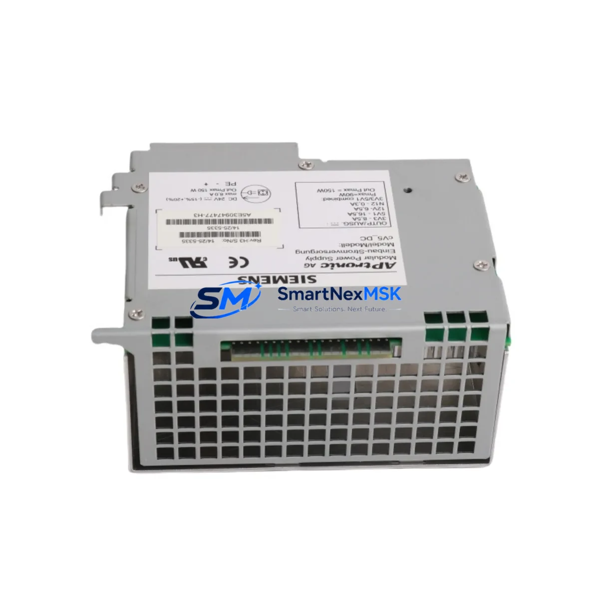
Siemens A5E30947477 Retrofit-Ready Power Supply for SIMATIC S7 Control Systems
The Siemens A5E30947477 is a proven power supply module engineered for seamless integration into SIMATIC S7-300 and compatible control system architectures. As legacy automation infrastructure ages and original components reach end-of-life, the A5E30947477 serves as a reliable retrofit solution — enabling engineers to restore, upgrade, and future-proof existing control cabinets without redesigning the entire electrical panel or reprogramming the PLC logic from scratch.
Whether you are replacing a failed 6ES7307-1EA01-0AA0 or a discontinued 6ES7307-1KA02-0AA0 power supply in an S7-300 rack, or migrating a legacy S5 system toward a modern S7 platform, the A5E30947477 provides the electrical compatibility, DIN rail footprint, and terminal layout that field engineers require for a controlled, low-risk cutover. Its 24 VDC output and standard backplane interface make it directly interchangeable with a wide range of Siemens SITOP and S7-series power modules, reducing procurement lead time and simplifying spare parts inventory management.
Upgrade Compatibility Table
| Parameter | Details |
|---|---|
| Compatible Series | SIMATIC S7-300, S7-400 (with adapter), ET 200M distributed I/O |
| Replaces | 6ES7307-1EA01-0AA0, 6ES7307-1KA02-0AA0, A5E00859485, A5E01112988 |
| Output Voltage | 24 VDC regulated |
| Mounting | DIN rail (35 mm), standard S7-300 profile rail compatible |
| Terminal Wiring | Screw-type terminals; L+, M, PE — matches original wiring diagram |
| Backplane Interface | Direct bus connector; no adapter required for S7-300 racks |
| Communication Compatibility | MPI, PROFIBUS DP (via CPU); no protocol change required |
| Commissioning Note | Verify CPU firmware version; re-download program if CPU memory was cleared |
| Installation Requirement | Power off entire rack before module swap; discharge capacitors before handling |
| Warranty | 12 months from date of shipment |
Retrofit Planning for Existing Automation Systems
A successful retrofit begins well before the module arrives on-site. When planning a power supply replacement in an S7-300 control cabinet, engineers must first audit the existing rack configuration. A typical S7-300 installation includes a CPU 315-2 DP or CPU 317-2 PN/DP mounted in a 6ES7390-1AE80-0AA0 profile rail, supported by a combination of digital input modules such as the SM 321 (6ES7321-1BH02-0AA0), digital output modules such as the SM 322 (6ES7322-1BH01-0AA0), and analog I/O modules from the SM 331/332 family. Each of these modules draws current from the backplane bus, and the total current budget must be recalculated before selecting a replacement power supply.
The A5E30947477 supports the current load requirements of standard S7-300 rack configurations. However, if the existing installation includes high-density I/O expansion racks connected via IM 360/361 interface modules, or if a CP 343-1 Ethernet communication processor or CP 342-5 PROFIBUS module is installed, the aggregate current draw must be verified against the module’s rated output capacity. Undersized power supplies are a leading cause of intermittent CPU faults and unexplained program stops in aging systems.
For systems that include a SIMATIC HMI TP700 Comfort or KTP900 Basic panel connected via PROFINET or MPI, the HMI configuration file should be backed up before any hardware swap. After replacing the power supply and restarting the CPU, verify that the HMI communication link re-establishes automatically. If the CPU address or rack slot assignment has changed, the HMI project may require a connection parameter update and re-download via TIA Portal or WinCC flexible.
Programming cables such as the PC Adapter USB A2 (6ES7972-0CB20-0XA0) should be on-hand during commissioning to allow direct CPU access for online diagnostics, force table verification, and program comparison between the backup and the live CPU. Always maintain a verified offline backup of the S7 project in STEP 7 or TIA Portal before initiating any hardware replacement.
Downtime Control During System Migration
Minimizing unplanned downtime is the primary concern for any industrial retrofit. When replacing the A5E30947477 or an equivalent power supply in a live production environment, the recommended approach is a planned maintenance window during a scheduled shift change or weekend shutdown. Before powering down the rack, use the CPU’s online diagnostic buffer in STEP 7 or TIA Portal to capture the current system state, including any pending alarms, active force values, and I/O status.
Once the rack is de-energized, photograph the existing terminal wiring before disconnecting any conductors. The A5E30947477 uses the same L1, N, PE input terminal layout as the original module, so re-wiring is straightforward. After installing the replacement module and restoring power, the CPU should perform a cold restart automatically if the memory card is intact. Verify the RUN/STOP LED status and check the diagnostic buffer for any new fault entries before releasing the system back to production.
For systems where continuous operation is critical, consider staging a pre-configured spare rack with the A5E30947477 already installed and tested offline. This hot-swap preparation strategy reduces the actual cutover window to under 30 minutes in most S7-300 installations, preserving production continuity and reducing the risk of commissioning errors under time pressure.
Retrofit Support FAQ
Q1: Is the A5E30947477 a direct drop-in replacement for the 6ES7307-1EA01-0AA0?
Yes. The A5E30947477 shares the same DIN rail mounting profile, terminal block layout, and 24 VDC output specification as the 6ES7307-1EA01-0AA0. No wiring modifications or rack adapters are required for standard S7-300 installations. Verify the input voltage range (120/230 VAC) matches your local supply before installation.
Q2: Will my existing STEP 7 or TIA Portal program run without modification after the swap?
In most cases, yes. The power supply module does not store program logic; the CPU retains the program on its memory card or internal flash. After replacing the power supply and restarting the CPU, the program should resume from the last saved state. If the CPU performs a complete memory reset (indicated by the STOP LED flashing), re-download the program from your backup project.
Q3: What wiring checks should be performed before powering up the replacement module?
Confirm that L1 (line), N (neutral), and PE (protective earth) are connected to the correct terminals and that all screw terminals are torqued to the specified value (typically 0.5–0.6 Nm for S7-300 power supply terminals). Check that the output 24 VDC terminals are correctly connected to the backplane bus connector and any external 24 VDC loads. Measure input voltage with a multimeter before energizing.
Q4: What does the 12-month warranty cover?
All A5E30947477 units shipped by SMARTNEXMSK are covered by a 12-month warranty from the date of shipment. The warranty covers manufacturing defects and functional failures under normal operating conditions. Units showing signs of physical damage, incorrect installation, or operation outside rated specifications are not covered. Contact [email protected] to initiate a warranty claim or request a pre-shipment test report.
© 2026 SMARTNEXMSK. All rights reserved.
Original Source: https://smartnexmsk.com
Contact: [email protected] | +86 18259474341



