
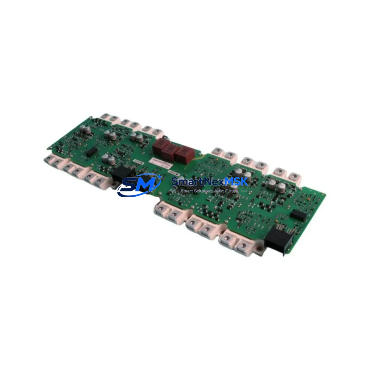
Siemens A5E42740246 Retrofit-Ready Power Unit for S120 Control Systems
The Siemens A5E42740246 is a retrofit-ready Power Unit designed for seamless integration into SINAMICS S120 drive systems. Whether you are replacing an end-of-life component in an aging production line, upgrading a legacy control cabinet, or restoring a system after an unplanned failure, the A5E42740246 delivers verified electrical compatibility, reliable DC bus performance, and the mechanical fit required for direct installation into existing S120 booksize or chassis configurations.
Industrial facilities running SINAMICS S120 platforms often face the challenge of sourcing replacement power-stage components that match original wiring layouts, DC link voltage ratings, and firmware handshake requirements. The A5E42740246 addresses these needs directly. Its terminal block layout is consistent with the original Siemens engineering drawings, reducing rewiring time during changeover. The unit interfaces with the S120 Control Unit — such as the CU320-2 DP or CU320-2 PN — via the DRIVE-CLiQ communication link, preserving existing topology data and drive object assignments without requiring a full parameter reset.
Before installation, engineers should verify the incoming AC supply voltage, confirm that the Line Module or Active Line Module upstream in the cabinet is rated to support the A5E42740246’s input current demand, and check that the DC bus capacitor pre-charge circuit is functioning correctly. The Braking Module or Smart Line Module in the same rack should also be inspected to ensure coordinated energy recovery behavior is maintained after the swap.
Upgrade Compatibility Table
| Parameter | Details |
|---|---|
| Compatible Series | SINAMICS S120 Booksize / Chassis |
| Communication Interface | DRIVE-CLiQ |
| Control Unit Compatibility | CU320-2 DP, CU320-2 PN |
| DC Bus Interface | Standard S120 DC link busbar |
| Mounting / Installation | Direct rack mount; compatible with S120 booksize backplane |
| Terminal Wiring | Matches original S120 terminal layout; minimal rewiring required |
| Firmware Compatibility | Compatible with STARTER / SINAMICS Startdrive commissioning tools |
| Replacement Recommendation | Drop-in replacement for equivalent S120 Power Unit variants |
| Commissioning Tool | SINAMICS Startdrive (TIA Portal) or STARTER V5.x |
| Warranty | 12 Months from date of shipment |
Retrofit Planning for Existing Automation Systems
A successful retrofit of the A5E42740246 into an operating S120 system requires a structured pre-installation review. Begin by auditing the existing cabinet layout: confirm that the S120 booksize backplane or chassis frame has the correct slot assignment for the Power Unit, and that adjacent modules — including the Motor Module, Double Motor Module, or Capacitor Module — are seated correctly and show no fault codes on the BOP20 operator panel or the CU320-2 control unit display.
Next, review the power supply chain. The incoming 3-phase AC feed to the Line Module must be within the rated voltage tolerance band. If the system uses an Active Line Module for regenerative braking, verify that the AFE (Active Front End) firmware version is compatible with the replacement unit’s hardware revision. The 24 VDC auxiliary supply — typically sourced from a SITOP PSU8600 or equivalent power supply module — must be stable before powering up the new unit, as the DRIVE-CLiQ enumeration sequence depends on a clean low-voltage rail.
For systems that include a Sensor Module Cabinet-Mounted (SMC) for encoder feedback, confirm that the encoder cable routing and SMC address assignments are unchanged. If the retrofit involves migrating from PROFIBUS DP to PROFINET IO — for example, replacing a CU320-2 DP with a CU320-2 PN — the A5E42740246 will continue to operate transparently at the power stage level, but the PLC program on the SIMATIC S7-300 or S7-1500 controller will require updated device configuration and GSD/GSDML file imports. The HMI screens on a connected SIMATIC HMI TP700 or TP1200 panel should also be reviewed to ensure that drive status tags and fault message displays remain mapped correctly after the topology change.
Wiring adaptation kits, if required for terminal pitch differences between old and new units, should be prepared in advance. All shield connections at the PE terminal strip must be verified to maintain EMC compliance, particularly in high-frequency drive environments where conducted emissions can affect nearby I/O modules or communication cables.
Downtime Control During System Migration
Minimizing production downtime during a Power Unit replacement is a primary concern for maintenance teams. The recommended approach is to pre-configure the replacement A5E42740246 offline using SINAMICS Startdrive before the scheduled maintenance window. Upload the existing drive parameter set from the CU320-2 using the “Upload to PG/PC” function in TIA Portal, then verify that all relevant parameters — including ramp times, current limits, speed setpoints, and safety function configurations — are correctly stored in the project file.
During the physical swap, isolate the drive system using the upstream circuit breaker or main contactor, discharge the DC bus fully (confirm with a calibrated voltage meter — do not rely solely on the discharge indicator LED), and document the existing terminal connections with photographs before disconnecting any wiring. After installing the A5E42740246, reconnect all terminals per the original wiring diagram, re-engage the DRIVE-CLiQ cables, and restore the 24 VDC supply. The CU320-2 will automatically re-enumerate the new Power Unit via DRIVE-CLiQ and assign it to the existing drive object if the component order in the topology has not changed.
Download the saved parameter set to the new unit, perform a function test at reduced speed setpoint, and verify motor rotation direction, encoder feedback signal, and fault-free operation before returning the system to full production speed. For safety-integrated axes, re-acknowledge the Safety Integrated functions and confirm that the STO (Safe Torque Off) and SS1 (Safe Stop 1) responses are operating correctly. The entire planned replacement procedure, when pre-staged, can typically be completed within a single 4–8 hour maintenance shift, keeping unplanned downtime to a minimum.
Retrofit Support FAQ
Q1: Is the A5E42740246 a direct drop-in replacement for my existing S120 Power Unit?
In most S120 booksize configurations, yes. The A5E42740246 shares the standard DC bus interface, DRIVE-CLiQ connector, and terminal layout with compatible S120 Power Unit variants. However, you should confirm the hardware revision and rated output current of your existing unit against the A5E42740246 datasheet before installation to ensure full electrical equivalence.
Q2: Do I need to re-enter all drive parameters after replacing the Power Unit?
No. The drive parameters are stored in the CU320-2 Control Unit, not in the Power Unit itself. As long as the Control Unit is retained and the DRIVE-CLiQ topology is unchanged, the existing parameter set will be automatically applied to the replacement A5E42740246 upon power-up. A parameter backup prior to the swap is still strongly recommended as a precaution.
Q3: What commissioning steps are required after installation?
After physical installation and wiring verification, power up the 24 VDC auxiliary supply and confirm that the CU320-2 recognizes the new Power Unit in the DRIVE-CLiQ topology. Use SINAMICS Startdrive or STARTER to perform a “Compare Offline/Online” check, download any parameter differences, and run a no-load function test. For safety-integrated drives, re-acknowledge all Safety Integrated functions and document the test results per your site’s commissioning protocol.
Q4: What does the 12-month warranty cover, and how is it handled?
The A5E42740246 is supplied with a 12-month warranty from the date of shipment, covering manufacturing defects and component failures under normal operating conditions. Each unit undergoes pre-shipment functional testing before dispatch. In the event of a warranty claim, contact our technical support team with the unit serial number and fault description. Replacement or repair will be arranged promptly to minimize your system downtime.
© 2026 SMARTNEXMSK. All rights reserved.
Original Source: https://smartnexmsk.com
Contact: [email protected] | +86 18259474341



