
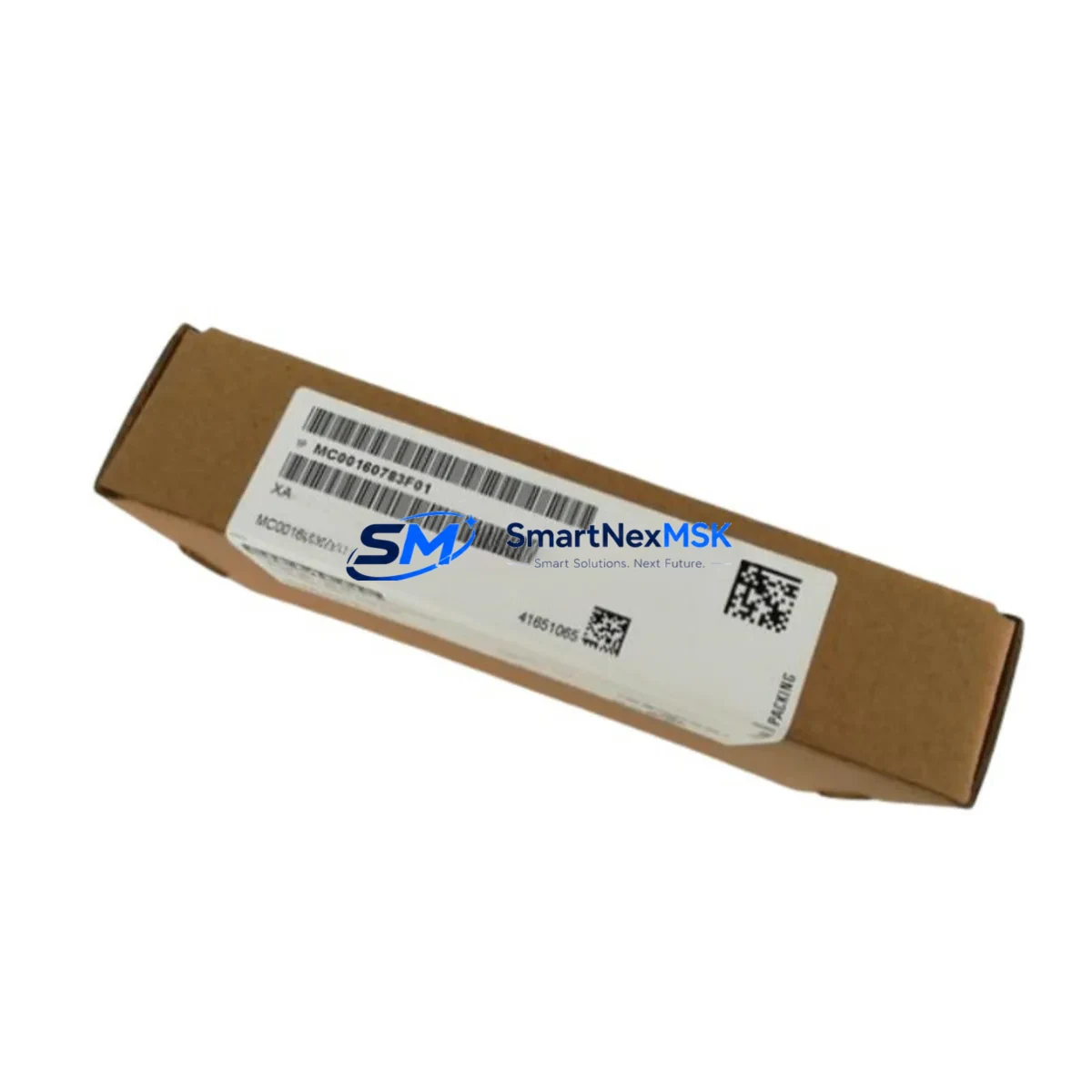
Siemens MC00160783G01/F01/M01 Retrofit-Ready Drive Control Board for SIMOVERT MASTERDRIVES 6SE70 Control Systems
The Siemens MC00160783G01/F01/M01 is a retrofit-ready drive control board engineered for seamless integration into existing SIMOVERT MASTERDRIVES 6SE70 variable frequency drive systems. As legacy 6SE70 platforms approach end-of-life and original spare parts become increasingly scarce, this board provides a verified drop-in replacement path that preserves your existing control architecture, minimizes engineering rework, and eliminates the need for full drive cabinet replacement. Whether you are managing a planned upgrade cycle or responding to an unplanned failure on a critical production line, the MC00160783G01/F01/M01 is stocked and ready for immediate dispatch with a 12-month warranty.
Industrial facilities running SIMOVERT MASTERDRIVES 6SE70 series drives — including the 6SE7021, 6SE7023, 6SE7031, and 6SE7033 frame sizes — frequently encounter control board failures caused by capacitor aging, IGBT gate driver degradation, or firmware corruption. In these scenarios, replacing only the control board rather than the entire drive unit delivers significant cost savings and dramatically reduces downtime. The MC00160783G01/F01/M01 is compatible across the F01 and M01 hardware revisions, making it suitable for a broad installed base without requiring firmware re-flashing in most standard configurations.
Upgrade Compatibility Table
| Parameter | Details |
|---|---|
| Compatible Drive Series | SIMOVERT MASTERDRIVES 6SE70 (6SE7021 / 6SE7023 / 6SE7031 / 6SE7033) |
| Hardware Revisions | F01, M01 |
| Backplane Interface | Standard 6SE70 control board slot — direct plug-in, no adapter required |
| Communication Compatibility | PROFIBUS-DP (CBP2), USS protocol via RS485, optional SIMOLINK |
| Power Supply Requirement | 24 VDC auxiliary supply from drive PSU — verify PSU capacity before swap |
| Terminal Wiring | Retain existing terminal block wiring; re-confirm analog I/O scaling after replacement |
| Replacement Recommendation | Direct replacement; parameter backup via DriveMonitor or STARTER recommended before swap |
| Commissioning Focus | Re-load parameter set P0 to P999; verify motor data, ramp times, and fault history reset |
| Warranty | 12 Months — covers manufacturing defects and functional failure under normal operating conditions |
Retrofit Planning for Existing Automation Systems
Successful retrofit of the MC00160783G01/F01/M01 into a live production environment requires careful pre-planning across several system layers. Before removing the failed board, engineers should use Siemens DriveMonitor or the STARTER commissioning tool to perform a full parameter upload from the drive, preserving motor nameplate data, PID loop settings, ramp-up and ramp-down profiles, and any application-specific function blocks stored in the drive’s non-volatile memory.
The 6SE70 drive cabinet typically houses additional components that must be inspected during the retrofit window. The 6SE70 power supply module (PSU) should be load-tested to confirm it can sustain the 24 VDC auxiliary rail under full control board load. The CUVC or CUMC control unit — which interfaces directly with the MC00160783G01/F01/M01 — should be inspected for corrosion on the backplane connector pins. If the system uses a CBP2 PROFIBUS communication board, verify that the DP address switches are correctly set and that the GSD file loaded in the Siemens S7-300 or S7-400 PLC project matches the drive’s firmware revision.
For systems where the 6SE70 drive communicates upstream to a Siemens S7-315 or S7-416 controller via PROFIBUS, the PLC program’s drive parameter channel (PKW) and process data channel (PZD) word assignments must be validated after the board swap. Any changes to the control word (STW) or status word (ZSW) bit mapping can cause unexpected drive behavior during the first power-on sequence. It is strongly recommended to perform the initial commissioning in local control mode before switching to remote PLC control.
In multi-drive cabinet installations, the retrofit may also involve re-checking the SIMOLINK fiber-optic ring topology if the 6SE70 units are daisy-chained for coordinated motion. The SLB (SIMOLINK Board) fitted to adjacent drives should be verified for ring continuity before and after the board replacement. Additionally, if the system includes a Siemens OP7 or OP17 HMI panel connected to the drive via the AOP (Advanced Operator Panel) port, the HMI screen parameter assignments should be re-validated to ensure drive status words are correctly mapped to display elements.
Terminal wiring on the CU (Control Unit) side — including digital inputs DI1–DI6, digital outputs DO1–DO3, analog inputs AI1–AI2, and analog outputs AO1–AO2 — should be documented with a wiring photograph before disconnection. After installing the MC00160783G01/F01/M01, re-terminate each signal wire to its original terminal and verify signal levels with a multimeter before enabling the drive. Pay particular attention to the enable signal (terminal 5) and the fault reset input to avoid nuisance trips during the first run.
Downtime Control During System Migration
Minimizing production downtime during a drive control board replacement requires a structured hot-swap protocol. Begin by scheduling the replacement during a planned maintenance window and pre-staging all required tools: ESD wrist strap, torque screwdriver, parameter backup file, and the replacement MC00160783G01/F01/M01 board. Confirm that the replacement board has been pre-tested at our facility and ships with a functional test report.
Before de-energizing the drive, issue a controlled stop command from the PLC or DCS to bring the motor to a safe standstill. Isolate the drive using the upstream circuit breaker and verify zero voltage on the DC bus using a calibrated meter — the 6SE70 DC bus can retain charge for several minutes after power-off. Once isolation is confirmed, remove the failed control board by releasing the front panel latch and sliding the board out of the backplane slot. Install the MC00160783G01/F01/M01, ensuring the backplane connector is fully seated.
After power restoration, download the previously saved parameter set using DriveMonitor. Perform a motor identification run (P1910) if motor data was not previously stored, then execute a ramp function test at reduced speed before returning the drive to full production load. This sequence typically allows a complete board swap and recommissioning to be completed within a 2–4 hour maintenance window, preserving the original control logic and protecting production continuity.
Retrofit Support FAQ
Q1: Is the MC00160783G01/F01/M01 a direct drop-in replacement for the original Siemens board in my 6SE70 drive?
Yes. The MC00160783G01/F01/M01 is designed as a direct plug-in replacement for the original control board in SIMOVERT MASTERDRIVES 6SE70 series drives. No mechanical modifications or adapter brackets are required. Hardware revisions F01 and M01 are both supported.
Q2: Do I need to re-enter all drive parameters after replacing the board?
Yes, parameter memory is stored on the control board. We strongly recommend performing a parameter backup using Siemens DriveMonitor or STARTER before removing the failed board. After installing the replacement, the saved parameter file can be downloaded directly to restore all motor data, ramp settings, and application configurations.
Q3: What communications protocols are supported, and will my existing PROFIBUS network work without reconfiguration?
The MC00160783G01/F01/M01 supports PROFIBUS-DP via the CBP2 communication board, USS protocol over RS485, and SIMOLINK fiber-optic communication. In most cases, the existing PROFIBUS configuration and GSD file remain valid after the board swap, provided the firmware revision is compatible. Verify the DP node address setting on the CBP2 board after installation.
Q4: What does the 12-month warranty cover, and how is it handled?
The 12-month warranty covers manufacturing defects and functional failures under normal industrial operating conditions. If the board fails within the warranty period, we provide a replacement unit or full refund after fault verification. All boards are functionally tested before shipment and ship with a test report. Contact [email protected] for warranty claims or pre-sales technical support.
© 2026 SMARTNEXMSK. All rights reserved.
Original Source: https://smartnexmsk.com
Contact: [email protected] | +86 18259474341



