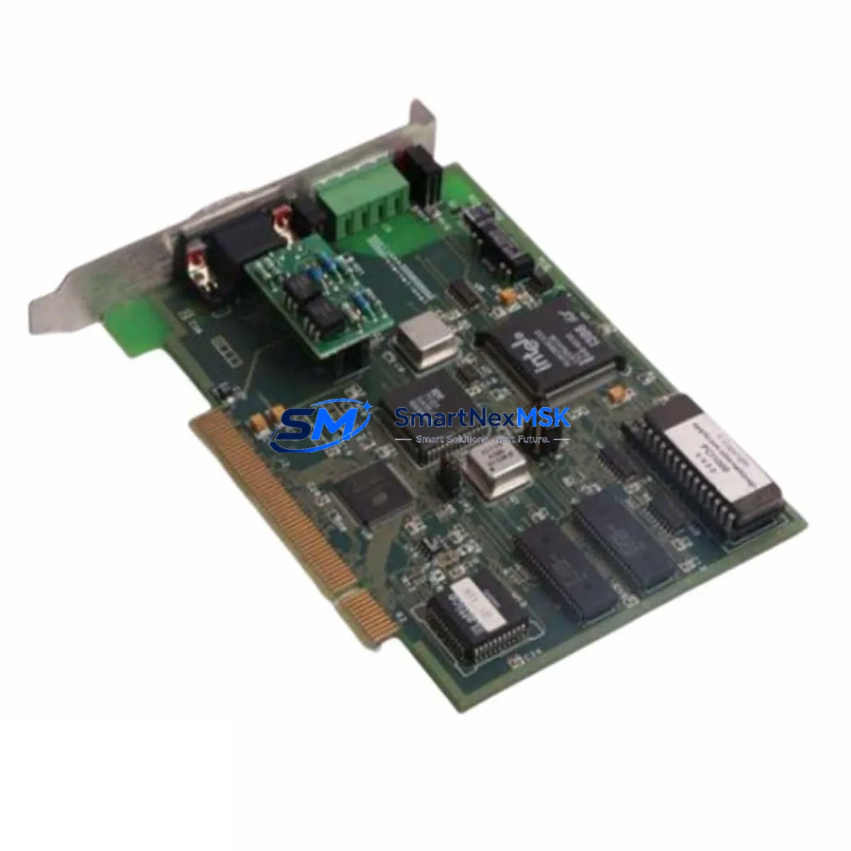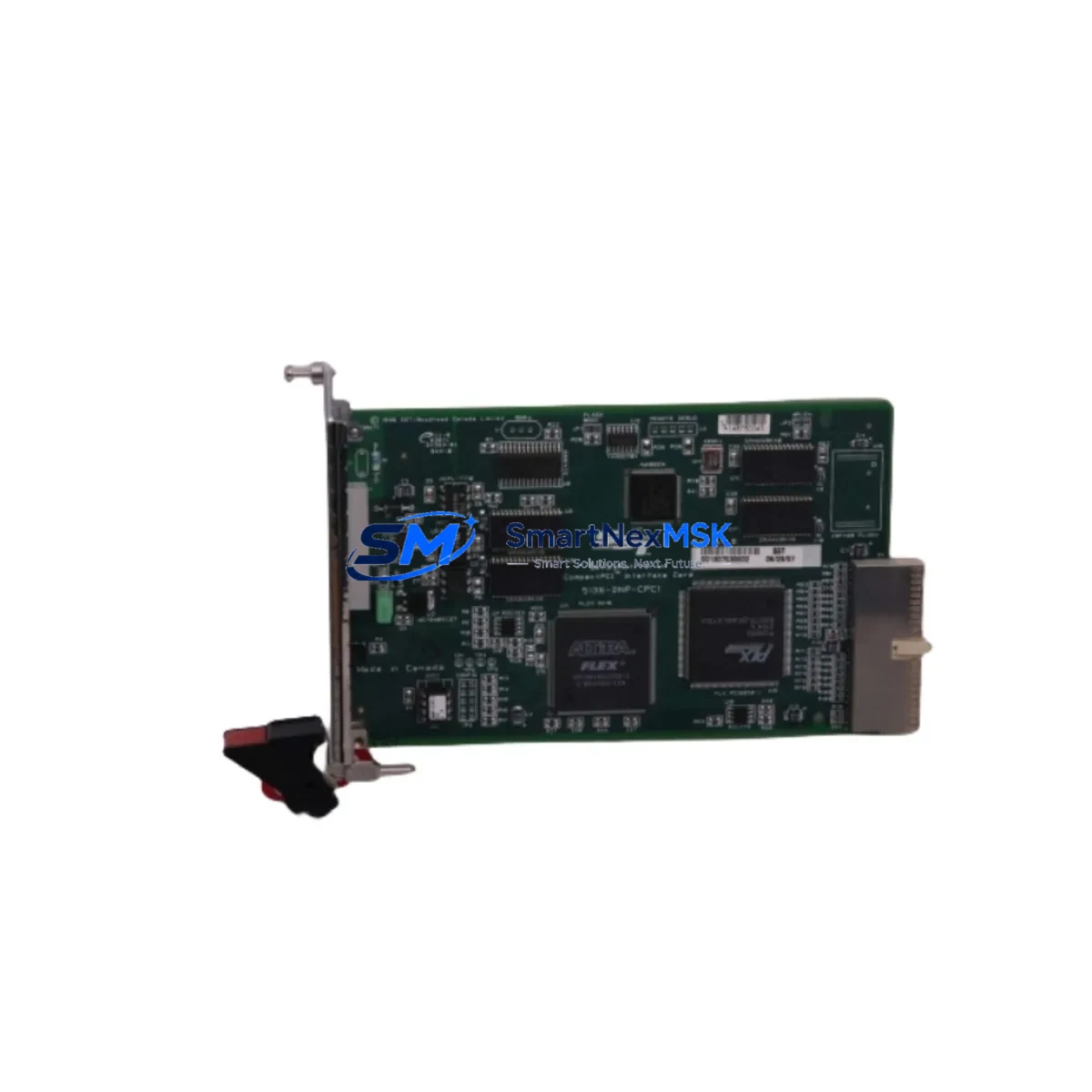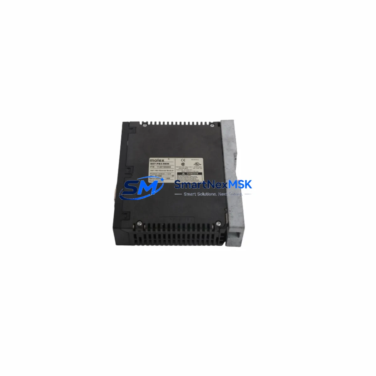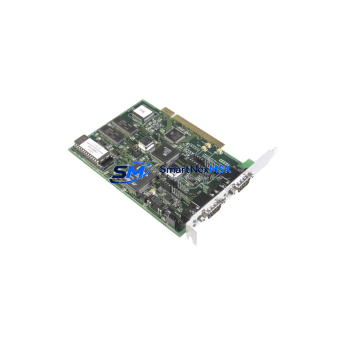
SST APP-PS7-PCU-C Maintenance-Ready Spare for S7 Automation
The SST APP-PS7-PCU-C is an original PROFIBUS PCU (Processor and Communication Unit) power supply module engineered for Siemens S7-300 series backplane environments. In industrial automation facilities where PROFIBUS DP networks underpin critical process control, an unplanned failure of this module can cascade into full-line shutdowns within minutes. Stocking a verified spare of the APP-PS7-PCU-C is therefore not a luxury — it is a core element of any responsible maintenance strategy for S7-based control architectures.
Sourced directly through authorised distribution channels, every unit supplied by SMARTNEXMSK undergoes pre-shipment functional verification covering power rail output stability, PROFIBUS interface integrity, and backplane connector condition. The module ships with a 12-month warranty and full traceability documentation, giving maintenance engineers and procurement teams the confidence to hold it as a long-term shelf spare without concern over counterfeit risk or degraded shelf life.
Spare Maintenance Table
| Parameter | Specification / Detail |
|---|---|
| Part Number | APP-PS7-PCU-C |
| Brand | SST (Woodhead / Molex SST) |
| Series | APP-PS7 — PROFIBUS S7 Interface Series |
| Function | PROFIBUS DP PCU Power & Communication Unit for S7-300 Backplane |
| Bus Compatibility | PROFIBUS DP (EN 50170), Siemens S7-300 backplane slot |
| Power Input | 24 V DC (nominal), per S7-300 backplane power rail specification |
| Communication Interface | PROFIBUS DP, 9-pin Sub-D connector |
| Installation | DIN-rail mounted via S7-300 backplane; no additional mounting hardware required |
| Operating Temperature | 0 °C to +60 °C (standard industrial cabinet environment) |
| Ingress Protection | IP20 (for use inside control cabinet) |
| Weight | Approx. 2,500 g (packaged) |
| Origin | USA (SST / Molex SST manufacturing) |
| Condition | Original, new-in-box or factory-refurbished with test certificate |
| Warranty | 12 Months — covers manufacturing defects and functional failure |
| Pre-shipment Test | Power rail output, PROFIBUS DP link-up, backplane connector continuity |
| Typical Application | S7-300 PLC systems with PROFIBUS DP master/slave networks in process, discrete, and hybrid automation |
| Replacement Scenario | PCU power fault, PROFIBUS communication loss, backplane slot failure, planned preventive swap |
Maintenance Planning for Continuous Operation
When a maintenance or reliability engineer schedules a replacement of the APP-PS7-PCU-C, the intervention window should be used to inspect the entire S7-300 control cabinet systematically. Stopping at the PCU module alone is a missed opportunity — adjacent components in the same power and communication loop are subject to identical thermal cycling, vibration, and voltage transient stress.
Begin with the S7-300 24 V DC power supply module (e.g., PS 307 series) that feeds the backplane rail. A marginal power supply delivering slightly low voltage under load is a common root cause of intermittent PCU resets that are misdiagnosed as module failure. Measure output voltage under full backplane load before condemning the APP-PS7-PCU-C. Alongside the power supply, inspect the backplane bus connector and the U-connector links between rack segments — oxidised or cracked bus connectors are a frequent source of PROFIBUS segment faults in older S7-300 installations.
The PROFIBUS DP cable and termination resistors at both ends of the segment deserve close attention. A missing or double-terminated segment will cause the APP-PS7-PCU-C to report bus errors even after a successful module swap. Verify that the 9-pin Sub-D connectors on the PROFIBUS trunk are properly seated and that the termination switch on the last device in the segment is active. If the installation uses PROFIBUS repeaters to extend segment length or cross electrical isolation boundaries, check repeater status LEDs and power supply integrity at the same time.
On the I/O side, review the SM 321/SM 322 digital input and output modules installed in the same rack. These modules share the backplane power rail with the PCU and can exhibit latent faults — particularly blown channel fuses or degraded optocoupler isolation — that only become apparent after a PCU replacement restores clean bus communication. Similarly, any SM 331/SM 332 analogue I/O modules in the rack should be checked for drift or calibration errors that may have accumulated during the period of PCU instability.
If the S7-300 system communicates upstream via Industrial Ethernet using a CP 343-1 communications processor, confirm that the CP module’s firmware version is compatible with the restored PROFIBUS configuration. In multi-network cabinets, also inspect signal isolators and loop-powered barriers on 4–20 mA analogue loops connected to field instruments — these are often overlooked during PROFIBUS-focused maintenance but can introduce ground loops that corrupt analogue readings after a cabinet intervention. Finally, check the 24 V DC fuse terminals and miniature circuit breakers on the cabinet’s power distribution rail; a nuisance trip on a branch circuit during the PCU fault event may have left a field device de-energised without a corresponding alarm.
Site Replacement Workflow
Step 1 — Preparation and compatibility confirmation. Before ordering, confirm the exact backplane slot assignment and PROFIBUS DP address configured in the existing APP-PS7-PCU-C using the STEP 7 hardware configuration (HW Config). Note the GSD file version used for the SST PROFIBUS master interface, as this determines the parameter dataset that will be downloaded to the replacement module. SMARTNEXMSK can supply the correct GSD file on request.
Step 2 — Safe isolation. Follow your site’s Lockout/Tagout (LOTO) procedure. De-energise the 24 V DC backplane supply and confirm zero-energy state with a calibrated multimeter before removing the APP-PS7-PCU-C from the backplane slot. Do not hot-swap this module without confirming that the specific backplane and CPU firmware revision supports hot insertion.
Step 3 — Module removal and inspection. Remove the existing module and inspect the backplane slot connector for bent pins, corrosion, or debris. Clean with dry compressed air if necessary. Retain the old module for failure analysis — the diagnostic LEDs and internal fault log (accessible via SST diagnostic software) can confirm whether the failure was power-related, communication-related, or firmware-related.
Step 4 — Installation and parameter download. Insert the replacement APP-PS7-PCU-C into the correct backplane slot. Restore 24 V DC power and observe the module’s status LEDs. Download the PROFIBUS master configuration from STEP 7 HW Config. Verify that all slave devices on the PROFIBUS segment report online status in the diagnostic view before releasing the system to production.
Step 5 — Functional test and documentation. Perform a full I/O scan and confirm that all process values are within expected ranges. Update the maintenance log with the replacement date, new module serial number, and any observations from the failed unit. Replenish your spare parts inventory immediately — lead times for SST PROFIBUS modules can extend to several weeks through standard distribution channels. SMARTNEXMSK maintains ready stock to support emergency and planned replacement requirements.
Spare Parts Support FAQ
Q1: Is the APP-PS7-PCU-C still available as a new original spare, or only as a refurbished unit?
SMARTNEXMSK stocks both new-in-box original units and factory-refurbished units with full test certification. Each refurbished unit is restored to original specification, tested against SST’s functional test protocol, and supplied with a 12-month warranty identical to that of a new unit. The product listing specifies condition; contact [email protected] to confirm current stock status before ordering.
Q2: How do I verify compatibility with my existing S7-300 backplane configuration before installation?
Compatibility is determined by three factors: the backplane rack type (UR1, UR2, or ER1/ER2 expansion rack), the PROFIBUS DP address range configured in your STEP 7 project, and the GSD file version used for the SST master interface. Provide your STEP 7 HW Config export or a photograph of the existing module’s label to our technical team and we will confirm compatibility before shipment. No additional hardware adapters are required for standard S7-300 backplane installations.
Q3: What does the 12-month warranty cover, and what is the claims process?
The 12-month warranty covers all manufacturing defects and functional failures under normal operating conditions (24 V DC supply within ±10%, operating temperature 0–60 °C, installed in a clean IP20 cabinet environment). It does not cover damage caused by incorrect installation, overvoltage events, or physical impact. To initiate a warranty claim, contact [email protected] with the order number, module serial number, and a description of the fault symptom. SMARTNEXMSK will arrange return shipping and provide a replacement or repair within an agreed lead time.
Q4: Can SMARTNEXMSK support ongoing spare parts inventory programmes for multi-site S7-300 installations?
Yes. For customers operating multiple S7-300 PROFIBUS installations, SMARTNEXMSK offers scheduled replenishment agreements and priority stock reservation. This ensures that critical spares such as the APP-PS7-PCU-C, along with associated power supply modules, I/O modules, and PROFIBUS network components, are available for immediate dispatch when needed — without relying on spot-market availability or extended lead times from standard distribution. Contact our sales team to discuss volume pricing and inventory support terms.
© 2026 SMARTNEXMSK. All rights reserved.
Original Source: https://smartnexmsk.com
Contact: [email protected] | +86 18259474341