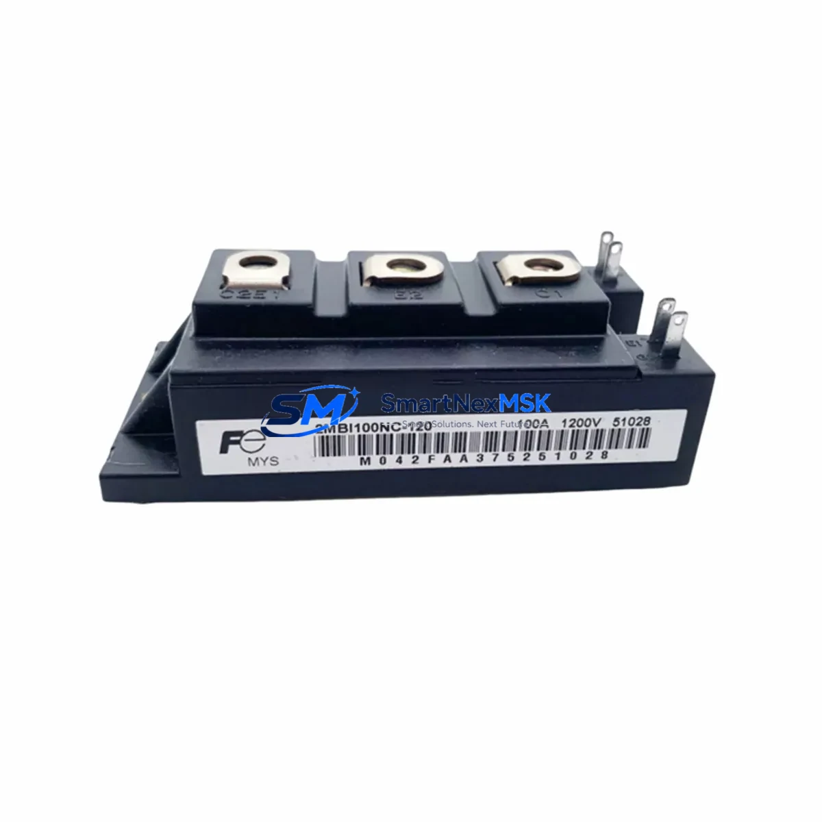
TOSHIBA 110Q2G43 Maintenance-Ready Spare for 110Q Automation
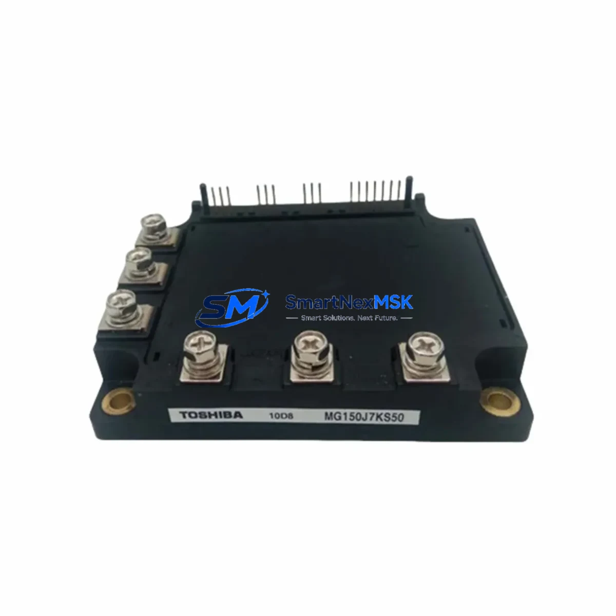
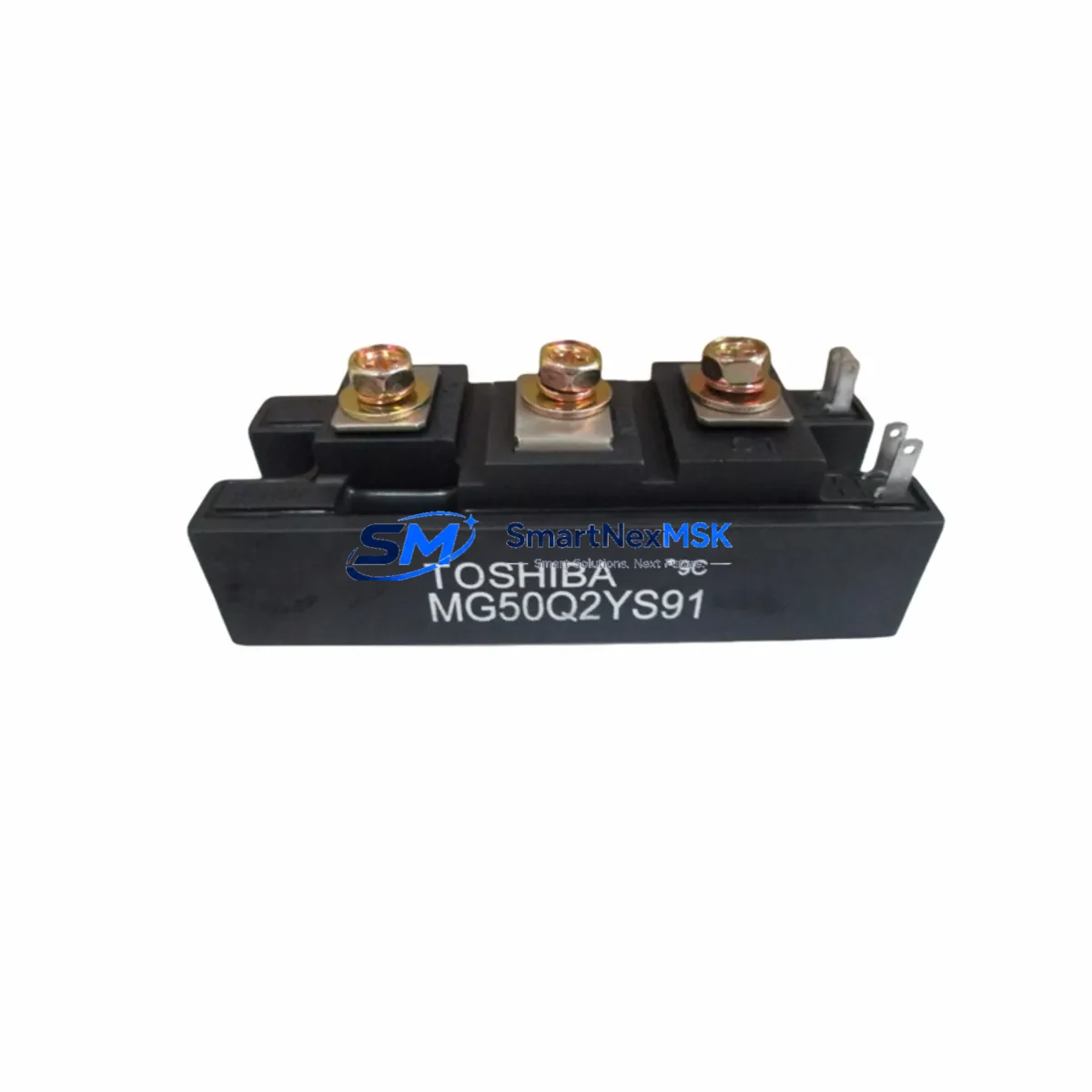
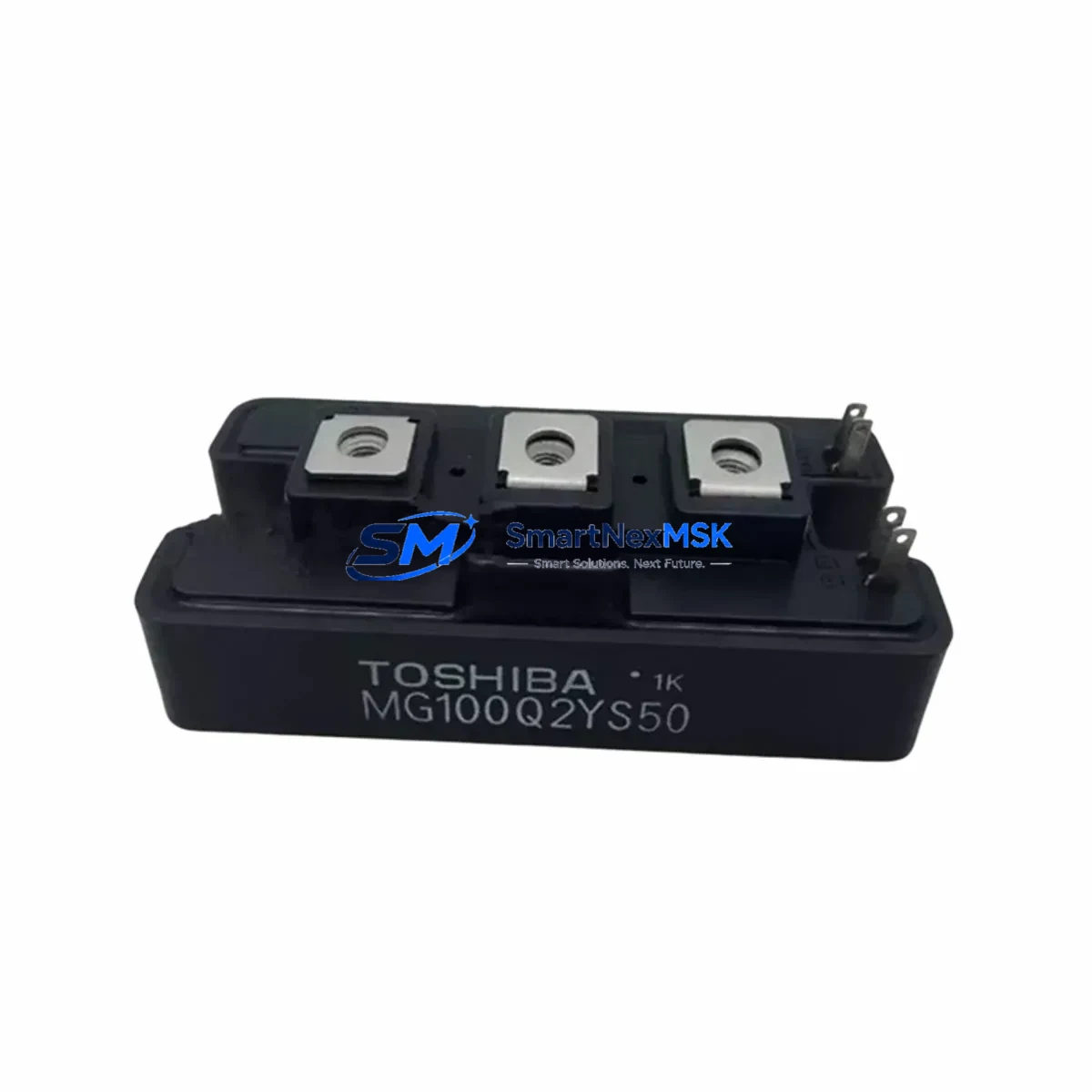
The TOSHIBA 110Q2G43 is a 1200V / 110A dual IGBT power module engineered for high-reliability industrial automation systems. As a direct original spare, it is the preferred replacement component for maintenance engineers managing variable frequency drives (VFDs), servo drive cabinets, and medium-voltage motor control centers where unplanned downtime carries significant operational cost. Whether you are executing a scheduled overhaul, responding to a fault alarm, or building a strategic spare parts inventory for aging 110Q-series drive systems, the 110Q2G43 delivers verified electrical performance, dimensional compatibility, and the confidence of a 12-month warranty backed by pre-shipment functional testing.
Industrial facilities running TOSHIBA VF-S15, VF-AS3, or equivalent 110Q-platform drives frequently encounter IGBT module degradation as the primary failure mode after 5–10 years of continuous operation. Thermal cycling, capacitive load transients, and inadequate heatsink maintenance accelerate junction fatigue. Stocking the 110Q2G43 as a ready-to-install spare eliminates the 4–12 week lead time associated with OEM procurement channels and keeps your production line or utility system operational.
Spare Maintenance Table
| Part Number / SKU | 110Q2G43 (TOSHIBA) |
| Module Type | Dual IGBT Power Module |
| Collector-Emitter Voltage (Vces) | 1200 V |
| Continuous Collector Current (Ic) | 110 A |
| Gate-Emitter Voltage (Vge) | ±20 V |
| Series Compatibility | TOSHIBA 110Q Series VFD & Servo Drive Platforms |
| Typical Applications | VFD output stage, servo amplifier, regenerative drive, UPS inverter bridge |
| Mounting / Package | Standard IGBT module footprint; direct bolt-down with thermal interface material |
| Cooling Interface | Flat baseplate; compatible with forced-air and liquid-cooled heatsinks |
| Origin | Japan (Original TOSHIBA manufacture) |
| Operating Temperature | –40°C to +150°C junction; storage –40°C to +125°C |
| Isolation Voltage | 2500 V AC (baseplate to terminals, 1 min) |
| Pre-Shipment Testing | Vce(sat), leakage current, gate threshold, and diode forward voltage verified |
| Warranty | 12 Months from date of shipment |
| Condition | Original New (OEM) |
Maintenance Planning for Continuous Operation
Replacing the 110Q2G43 in a drive cabinet is rarely an isolated task. Experienced maintenance engineers treat an IGBT module failure as a trigger for a broader cabinet inspection to prevent repeat failures and identify latent faults before they escalate. When removing and replacing the 110Q2G43, the following associated components should be inspected or replaced as part of the same maintenance window:
DC Bus Capacitors: Electrolytic capacitors in the DC link (typically 1000–3300 µF / 450–900 V) degrade in parallel with IGBT modules. Measure ESR and capacitance; replace if values deviate more than 20% from nameplate. Brands such as EPCOS B43310 or Nichicon LGX series are common in 110Q-platform drives.
Gate Drive Board / Driver PCB: The gate resistor network and optocoupler isolation (e.g., HCPL-316J or equivalent) on the driver board may have sustained overvoltage stress during the IGBT failure event. Inspect for burnt resistors, cracked solder joints, and degraded optocouplers before powering up the replacement module.
Snubber Capacitors and Discharge Resistors: Film snubber capacitors mounted across the IGBT terminals suppress switching transients. After a hard IGBT failure, these components should be checked for cracking or delamination.
Current Sensors and Hall-Effect Transducers: Phase current sensors (e.g., LEM LA 100-P or equivalent) mounted on the output busbars provide overcurrent protection signals to the control board. Verify sensor output linearity and zero-offset calibration after any power stage replacement.
Thermal Interface Material (TIM) and Heatsink: Remove all residual thermal compound from the heatsink mounting surface. Apply fresh high-performance TIM (e.g., Shin-Etsu X-23 or Dow TC-5026) to the 110Q2G43 baseplate before installation. Inspect heatsink fins for blockage and verify fan operation if forced-air cooled.
Input Rectifier Bridge: A three-phase rectifier module (e.g., SEMIKRON SKD 51 or equivalent) converts AC supply to DC bus. Diode forward voltage and reverse leakage should be checked; a weakened rectifier can cause DC bus ripple that stresses the replacement IGBT module.
Pre-charge Resistors and Contactors: The soft-start pre-charge circuit limits inrush current during power-up. Inspect pre-charge resistors for thermal discoloration and verify contactor contact resistance. A failed pre-charge circuit will destroy a new IGBT module within seconds of energization.
Control Power Supply Module: The 24 VDC SMPS supplying the control board and gate drivers (e.g., MEAN WELL MDR-60-24 or equivalent DIN-rail PSU) should be load-tested. Voltage ripple exceeding ±5% on the 24 V rail can cause erratic gate drive signals and premature IGBT failure.
I/O Terminal Blocks and Signal Wiring: Inspect all control-side terminal blocks (e.g., Phoenix Contact MKDS or Weidmüller WDU series) for loose connections, corrosion, and insulation degradation. Loose analog reference or enable signal wiring can cause nuisance trips that mask the root cause of the original failure.
Communication Module (if applicable): If the drive is integrated into a PROFIBUS, DeviceNet, or Modbus RTU network via a plug-in communication card, verify that the card seated correctly and that network communication is restored after the drive is powered up. Communication faults post-maintenance are a common source of unnecessary downtime extension.
Site Replacement Workflow
Step 1 — Isolation and Lockout/Tagout: De-energize the drive, apply LOTO, and wait a minimum of 10 minutes for DC bus capacitors to discharge below 50 V (verify with a calibrated multimeter before touching any internal components).
Step 2 — Document and Photograph: Photograph all wiring, busbar connections, and gate drive harness routing before disassembly. Label all connectors. Record the drive’s parameter set via the HMI keypad or PC tool before power-down if possible.
Step 3 — Remove the Faulty Module: Disconnect gate drive connectors and power terminals. Remove mounting bolts in the sequence specified in the drive service manual. Slide the 110Q2G43 out of the heatsink channel carefully to avoid damaging adjacent components.
Step 4 — Inspect and Prepare the Heatsink: Clean the heatsink surface, inspect for corrosion or mechanical damage, and apply fresh TIM as described above.
Step 5 — Install the Replacement 110Q2G43: Position the new module, torque mounting bolts to specification (typically 3–5 N·m for M5 bolts), reconnect power terminals, and reconnect gate drive harness. Verify polarity and connector orientation against your photographs.
Step 6 — Pre-Power Verification: With the drive isolated from the motor load, perform a static check: measure DC bus resistance across each IGBT position using a diode-test function. Confirm no short-circuit paths exist before energizing.
Step 7 — Controlled Power-Up and Test: Energize the drive with the motor disconnected. Verify DC bus voltage, check for fault codes, and confirm gate drive supply voltages. Reconnect the motor and perform a low-speed no-load run before returning to full production load.
This systematic workflow minimizes the risk of repeat failures, reduces total downtime from hours to under 90 minutes for a prepared maintenance team, and ensures the replacement 110Q2G43 operates within its rated parameters from the first power cycle.
Spare Parts Support FAQ
Q1: Is the 110Q2G43 a direct drop-in replacement for the original TOSHIBA module, or are parameter adjustments required?
The 110Q2G43 supplied is an original TOSHIBA OEM component with identical electrical and mechanical specifications to the factory-installed part. No parameter changes, firmware updates, or hardware modifications are required. The drive’s existing gate drive circuit, protection thresholds, and thermal management system are fully compatible with the replacement module.
Q2: How is the 110Q2G43 tested before shipment, and what does the 12-month warranty cover?
Every unit undergoes pre-shipment electrical verification including Vce(sat) measurement, gate threshold voltage, reverse diode forward voltage, and high-potential isolation testing. The 12-month warranty covers manufacturing defects and electrical parameter non-conformance under normal operating conditions. It does not cover damage resulting from incorrect installation, overvoltage events, or operation outside rated specifications.
Q3: What is the recommended spare parts stocking strategy for facilities running multiple 110Q-series drives?
For facilities with three or more 110Q-platform drives, we recommend maintaining a minimum of one 110Q2G43 module per drive in the critical spare inventory, plus one additional unit as a floating emergency spare. Pair this with stocked DC bus capacitors, a spare gate driver board, and a replacement 24 VDC control power supply to cover the most common failure modes and achieve sub-2-hour MTTR targets.
Q4: Can the 110Q2G43 be used to replace modules in third-party drives that use the same IGBT footprint and ratings?
The 110Q2G43 is a TOSHIBA-specific module. While its 1200V/110A ratings and physical footprint may be dimensionally similar to modules from other manufacturers, compatibility with non-TOSHIBA drive platforms must be verified against the target drive’s gate drive voltage, gate resistance, and protection circuit requirements before installation. Contact our technical team with your drive model number for a compatibility assessment prior to ordering.
—
© 2026 SMARTNEXMSK. All rights reserved.
Original Source: https://smartnexmsk.com
Contact: [email protected] | +86 18259474341