TRUMPF 18-06-66-00/21 Maintenance-Ready Spare for TruLaser Automation
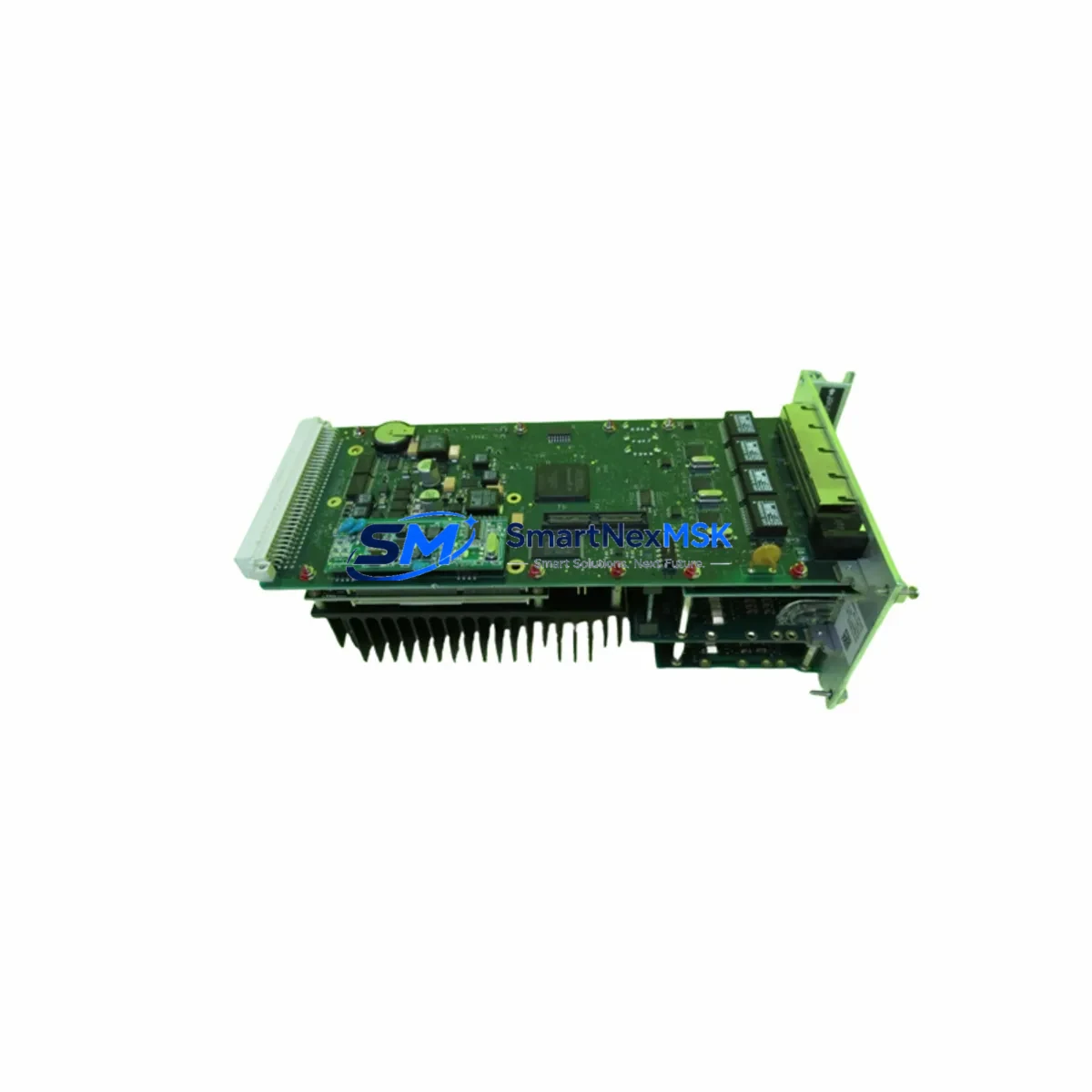
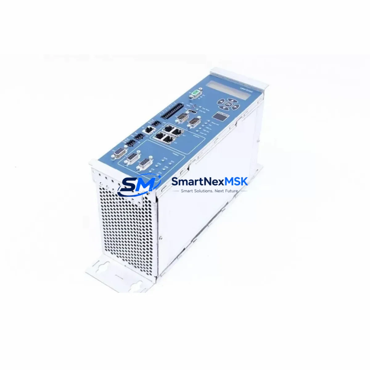
The TRUMPF 18-06-66-00/21 is an original-grade control PCB designed for TruLaser series laser cutting and automation systems. For maintenance engineers managing high-availability laser production lines, unplanned downtime caused by a failed control board can cascade into hours of lost output. Stocking a verified replacement of the 18-06-66-00/21 is a proven strategy to compress mean time to repair (MTTR) and restore cutting operations without waiting on extended lead times from OEM channels.
This board serves as the primary control interface within the TruLaser machine’s electrical cabinet, coordinating axis motion, laser power regulation, and I/O signal routing. When the 18-06-66-00/21 fails — typically presenting as axis faults, erratic laser triggering, or complete loss of machine response — a pre-qualified spare on the shelf means the difference between a two-hour recovery and a two-week procurement delay.
Each unit supplied by SMARTNEXMSK undergoes functional verification and burn-in testing prior to shipment. All boards are shipped with protective anti-static packaging and include a 12-month warranty covering manufacturing defects and functional failure under normal operating conditions. We maintain long-term inventory of this reference to support both emergency replacement and planned maintenance cycles.
Spare Maintenance Table
| Parameter | Specification |
|---|---|
| Part Number / SKU | 18-06-66-00/21 |
| Brand | TRUMPF |
| Compatible Series | TruLaser (TruLaser 3030, 5030, 5040, and related variants) |
| Component Type | Control PCB / Laser Machine Control Board |
| Origin | Germany |
| Operating Voltage | 24 VDC (nominal, per TruLaser cabinet standard) |
| Installation Location | Main electrical cabinet, control rack |
| Interface | Multi-axis I/O, laser trigger, fieldbus communication |
| Application Environment | Industrial laser cutting, sheet metal automation |
| Condition | New / Original-grade, tested before shipment |
| Warranty | 12 Months — functional defect coverage |
| Delivery | Global express; DHL / FedEx / UPS available |
| Maintenance Recommendation | Replace at first sign of axis fault, laser trigger error, or board-level alarm; inspect connectors and backplane seating on installation |
Maintenance Planning for Continuous Operation
When replacing the TRUMPF 18-06-66-00/21, a disciplined maintenance engineer will not stop at the board itself. The TruLaser electrical cabinet is an integrated system, and a failed control PCB is often accompanied by — or caused by — stress on adjacent components. A thorough site inspection should include the following areas:
Power Supply Module: Verify the 24 VDC TRUMPF power supply module feeding the control rack. Voltage ripple or transient spikes are a leading cause of PCB failure. If the power supply shows signs of aging — output instability, audible hum, or thermal discoloration — replace it concurrently with the 18-06-66-00/21 to prevent repeat failure.
I/O Expansion Modules: The TruLaser control architecture distributes digital and analog I/O across dedicated expansion modules mounted in the same cabinet. After replacing the control board, verify all I/O channels are responding correctly. Faulty I/O modules can generate false alarms that mask the root cause of the original fault.
Communication and Fieldbus Interface: Check the TRUMPF fieldbus communication module (PROFIBUS or EtherCAT depending on machine generation) for connector integrity and firmware version compatibility. A mismatch between the replacement board and the fieldbus module firmware can prevent successful machine restart.
Relay and Contactor Bank: Inspect the relay modules and contactors in the safety and interlock circuit. Worn relay contacts can introduce intermittent faults that are incorrectly attributed to the control PCB. Replace any relay showing contact resistance above specification.
Terminal Blocks and Wiring Harness: Inspect all terminal block connections on the control board harness. Loose or corroded terminals are a common source of signal noise that degrades PCB performance. Re-torque all terminals to specification and apply contact protection spray where corrosion is present.
Signal Isolation Modules: If the TruLaser system uses analog signal isolators between the control PCB and external sensors or drives, verify isolator output accuracy. Degraded isolation can introduce ground loops that damage control boards over time.
Fuse and Circuit Protection: Replace all fuses in the control circuit as a matter of course during a board-level repair. Fuses that have experienced a fault event — even without blowing — may have degraded current capacity. Use only TRUMPF-specified fuse ratings.
HMI and Operator Panel: After board replacement, perform a full HMI communication test. The TRUMPF operator panel communicates with the control board via a dedicated interface; verify that all screen functions, alarm acknowledgment, and parameter access are restored correctly.
Backplane and Rack Connectors: Inspect the backplane connector on the control rack for bent pins, oxidation, or mechanical damage. A damaged backplane connector will cause intermittent faults on the replacement board and is frequently overlooked during emergency repairs.
Axis Drive and Encoder Feedback: Verify servo drive status and encoder feedback signals on all axes after board replacement. A control board fault can sometimes be triggered by a drive overcurrent or encoder error upstream; confirm all drives are fault-free before returning the machine to production.
Site Replacement Workflow
Step 1 — Isolate and Document: Power down the TruLaser system via the main disconnect. Photograph the existing board installation, connector positions, and cable routing before removal. This documentation is critical for correct reinstallation of the 18-06-66-00/21 replacement.
Step 2 — Remove the Faulty Board: Disconnect all harness connectors in sequence, labeling each if not already marked. Remove the board from the rack using the appropriate extraction tool. Avoid flexing the board or touching exposed component surfaces.
Step 3 — Inspect the Slot and Backplane: Before installing the replacement, inspect the rack slot and backplane connector for damage or contamination. Clean with dry compressed air. Verify that the replacement board’s firmware version is compatible with the installed machine software version — consult the TRUMPF service documentation or contact SMARTNEXMSK for compatibility confirmation.
Step 4 — Install and Reconnect: Seat the 18-06-66-00/21 replacement firmly into the rack. Reconnect all harness connectors in the documented sequence. Verify connector locking clips are fully engaged.
Step 5 — Power-Up and Verify: Restore power and observe the boot sequence on the HMI. Confirm that no axis faults, communication errors, or I/O alarms are present. Run a dry-cycle test before resuming production cutting.
Step 6 — Update Maintenance Records: Log the replacement date, board serial number, and any associated findings in the machine maintenance record. Schedule a follow-up inspection at 500 operating hours to verify stable performance.
This workflow is designed to minimize total downtime and reduce the risk of repeat failure. SMARTNEXMSK recommends maintaining at least one spare 18-06-66-00/21 in the site spare parts inventory for TruLaser installations with high production utilization.
Spare Parts Support FAQ
Q1: Is the TRUMPF 18-06-66-00/21 compatible with all TruLaser machine generations?
The 18-06-66-00/21 is primarily associated with TruLaser 3030 and 5030/5040 series machines. Compatibility with specific machine serial number ranges depends on the control software version installed. SMARTNEXMSK can verify compatibility against your machine’s serial number and software version before shipment — contact us with your machine data for confirmation.
Q2: What testing is performed before shipment?
Every 18-06-66-00/21 unit undergoes functional power-on testing and signal integrity verification prior to dispatch. Units that do not pass testing are not shipped. A test report is available upon request for quality-critical procurement processes.
Q3: What does the 12-month warranty cover?
The 12-month warranty covers functional failure and manufacturing defects under normal operating conditions. It does not cover damage caused by incorrect installation, overvoltage events, or physical mishandling. In the event of a warranty claim, SMARTNEXMSK will provide a replacement unit or full refund after fault verification.
Q4: Can SMARTNEXMSK support long-term spare parts inventory for TruLaser systems?
Yes. SMARTNEXMSK maintains ongoing stock of the 18-06-66-00/21 and related TruLaser control components to support both emergency replacement and planned annual maintenance programs. We can provide blanket order arrangements and reserved stock agreements for customers with multiple TruLaser installations or high-frequency maintenance cycles.
© 2026 SMARTNEXMSK. All rights reserved.
Original Source: https://smartnexmsk.com
Contact: [email protected] | +86 18259474341