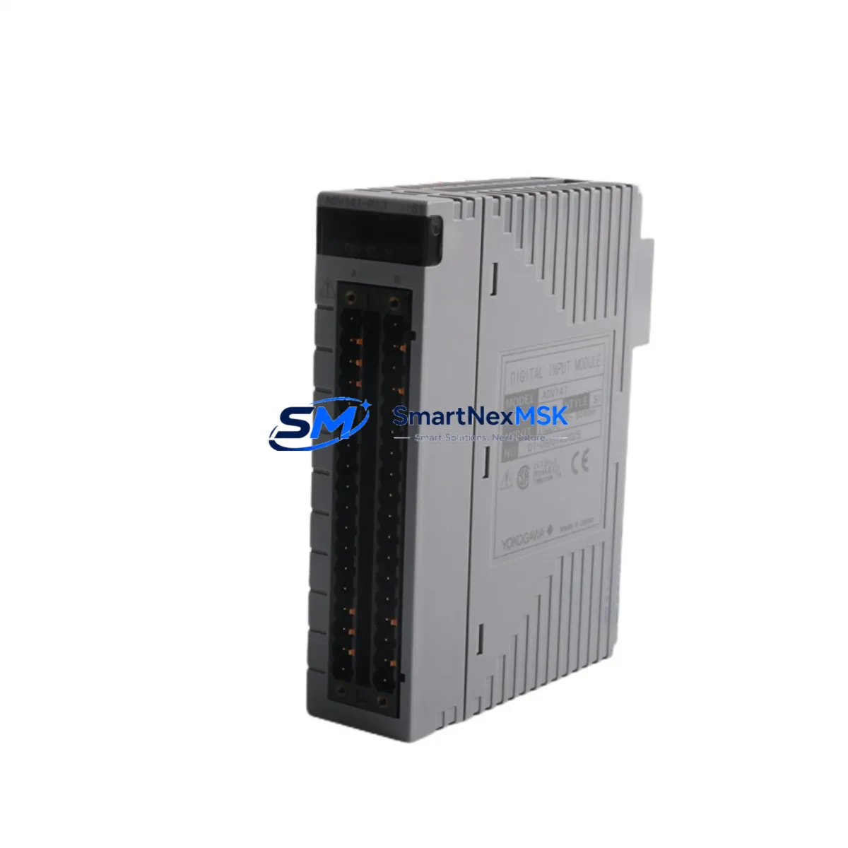
YOKOGAWA ADV141-P13 S1: Retrofit-Ready Digital Input Module for CENTUM VP Control Systems
The YOKOGAWA ADV141-P13 S1 is a 32-channel digital input module engineered for seamless integration into CENTUM VP and CENTUM CS 3000 distributed control systems. As legacy automation infrastructure ages and OEM support for discontinued components becomes increasingly scarce, the ADV141-P13 S1 stands as a proven, wiring-compatible replacement that enables plant engineers to modernize aging control cabinets without triggering a full system overhaul. Whether you are managing a scheduled turnaround, responding to an unplanned module failure, or executing a phased migration from CS 3000 to CENTUM VP R6, this module delivers the I/O density, signal compatibility, and backplane interface reliability that industrial facilities demand.
Sourced directly from verified supply channels and pre-tested prior to shipment, each ADV141-P13 S1 unit is backed by a 12-month warranty and ships from our Xiamen warehouse with full documentation support. Our inventory is maintained to support urgent replacement orders, minimizing the procurement lead time that often extends unplanned downtime in process-critical environments.
Upgrade Compatibility Table
| Parameter | ADV141-P13 S1 Specification | Retrofit Notes |
|---|---|---|
| Compatible Platform | CENTUM VP, CENTUM CS 3000 | Direct slot replacement; no firmware patch required for VP R4/R5/R6 |
| Channel Count | 32 DI channels | Verify field terminal block wiring matches 32-point layout before swap |
| Input Signal Type | Dry contact / Wet contact (24 VDC) | Confirm field device voltage; wet contact wiring requires no rewiring if replacing like-for-like |
| Backplane Interface | CENTUM VP I/O bus (standard node unit slot) | Compatible with RIO (Remote I/O) and local I/O node units; confirm node address assignment in HIS |
| Module Address | Slot-based auto-assignment | Re-confirm IOM address in CENTUM VP Engineering Environment after hot-swap or cold replacement |
| Communication Protocol | CENTUM VP internal V-net/IP or Vnet | No protocol migration required; module communicates natively on existing V-net backbone |
| HMI Compatibility | CENTUM VP HIS (Human Interface Station) | Existing faceplates and alarm tags remain valid; no HMI screen rebuild required |
| Replacement for | ADV141-P13 (earlier suffix variants) | S1 suffix denotes revised hardware revision; functionally equivalent for field replacement |
| Installation Requirement | Standard CENTUM VP node unit rack | No additional mounting hardware; slides into existing rack slot |
| Warranty | 12 Months | Covers manufacturing defects; includes pre-shipment functional test report on request |
Retrofit Planning for Existing Automation Systems
A successful retrofit of the ADV141-P13 S1 begins well before the module arrives on site. Plant engineers should start by auditing the existing node unit configuration within the CENTUM VP Engineering Environment, confirming the slot assignment, IOM tag name, and associated function block connections. In most CENTUM VP installations, the digital input module occupies a defined slot within a Node Unit (NU) or Remote Node Unit (RNU), and the replacement module must be inserted into the identical slot to preserve the IOM address without requiring a database rebuild.
Terminal block wiring is the next critical checkpoint. The ADV141-P13 S1 uses a standard CENTUM VP field terminal block, and in most cases the existing TB (Terminal Block) can remain in place, allowing the module swap to proceed without disturbing field wiring. However, engineers should verify that the terminal block suffix matches the ADV141-P13 S1 connector specification — mismatched terminal blocks are a common source of commissioning delays during legacy CS 3000 to CENTUM VP migrations.
Power supply capacity within the control cabinet must also be verified before installation. CENTUM VP node units draw regulated 24 VDC from the Power Supply Module (PSU) mounted within the same rack. When adding or replacing I/O modules during a cabinet upgrade, confirm that the existing PSU — such as the AVR121-S00 or equivalent — has sufficient headroom to support the additional load. Overloaded power supplies are a leading cause of intermittent module faults in retrofitted systems.
For facilities migrating from CENTUM CS 3000 to CENTUM VP, the ADV141-P13 S1 is compatible with the VP I/O bus architecture, but the migration plan should also account for the FCS (Field Control Station) firmware version and the associated Control Drawing (CD) database. Function blocks referencing the original DI module’s IOM tag will continue to operate correctly after replacement, provided the IOM address and tag name are preserved in the VP Engineering Environment. If the migration involves upgrading the FCS hardware — for example, replacing an FFCS-V (AFV10D) with a newer PFCS (AFP30D) — the I/O module database should be exported and validated before the cutover window.
Communication link integrity is equally important. CENTUM VP systems rely on the V-net/IP or legacy Vnet backbone to carry I/O data between the FCS and the HIS. Before replacing the ADV141-P13 S1, verify that the node unit’s communication status is healthy in the HIS System Overview window. A degraded V-net link can mask module faults and complicate post-replacement diagnostics. If the system uses ESB Bus (Extended Serial Backplane) for remote I/O expansion, confirm that the RIO node housing the ADV141-P13 S1 is communicating normally before and after the swap.
Finally, for facilities that also need to address adjacent I/O requirements during the same maintenance window, the ADV141-P13 S1 retrofit is often performed alongside replacement of analog input modules such as the AAI141-S03 or analog output modules such as the AAO141-S03, as well as digital output modules like the ADV551-P13. Grouping these replacements into a single planned outage reduces cumulative downtime and allows a single commissioning team to validate all affected control loops before returning the system to automatic mode.
Downtime Control During System Migration
Minimizing downtime during a CENTUM VP module replacement requires a structured pre-outage preparation protocol. Before taking the node unit offline, engineers should place all affected control loops into Manual (MAN) mode from the HIS, ensuring that field devices — valves, motors, and interlocks — are held at safe operating positions. The CENTUM VP system supports hot-standby FCS configurations, and where redundant FCS pairs are in use, the replacement can often be performed on the standby node without interrupting the primary control path.
The original application program — including all function block logic, tuning parameters, and interlock conditions — is stored in the FCS database and is not affected by a module-level hardware swap. Engineers do not need to reload or recompile the control application after replacing the ADV141-P13 S1, provided the IOM address and tag structure remain unchanged. This is a significant advantage over full controller replacements, where program migration and re-commissioning can extend outage windows by hours or days.
After the replacement module is seated and the node unit is powered, the CENTUM VP system will automatically re-scan the I/O bus and recognize the new module. Engineers should monitor the IOM Status Display in the HIS to confirm that all 32 DI channels return to normal status. Any channels showing fault conditions should be investigated at the field terminal block before returning loops to automatic control. A structured loop check — verifying each DI channel against its corresponding field device — should be completed and documented before the maintenance window is closed.
For facilities with strict change management requirements, a pre-tested spare ADV141-P13 S1 held in the site warehouse eliminates the procurement lead time entirely, reducing the replacement window to the time required for physical swap and loop verification — typically two to four hours for a 32-channel module in a well-documented system.
Retrofit Support FAQ
Q1: Is the ADV141-P13 S1 a direct replacement for earlier ADV141-P13 variants without suffix?
Yes. The S1 suffix denotes a hardware revision that is functionally equivalent to earlier ADV141-P13 variants. The module uses the same backplane connector, terminal block interface, and IOM address scheme. No changes to the CENTUM VP Engineering Environment database are required for a like-for-like replacement.
Q2: What wiring checks are required before installation?
Verify that the existing field terminal block is compatible with the ADV141-P13 S1 connector. Confirm field device signal type (dry contact or 24 VDC wet contact) matches the module’s input specification. Check that all field wiring is correctly labeled and that no open circuits or short circuits are present on the terminal block before inserting the new module.
Q3: Can this module be used in a CENTUM CS 3000 system?
The ADV141-P13 S1 is designed for CENTUM VP architecture. While some ADV-series modules share physical form factors with CS 3000 equivalents, compatibility must be verified against the specific CS 3000 node unit and backplane revision in use. Contact our technical team with your CS 3000 system configuration details for a confirmed compatibility assessment before ordering.
Q4: What does the 12-month warranty cover, and is a test report available?
The 12-month warranty covers manufacturing defects and functional failures under normal operating conditions. Each unit undergoes pre-shipment functional testing. A test report confirming channel-level verification can be provided upon request at the time of order. Warranty claims are processed through our Xiamen support team with a target response time of 48 hours.
© 2026 SMARTNEXMSK. All rights reserved.
Original Source: https://smartnexmsk.com
Contact: sales@smartnexmsk.com | +86 18259474341


