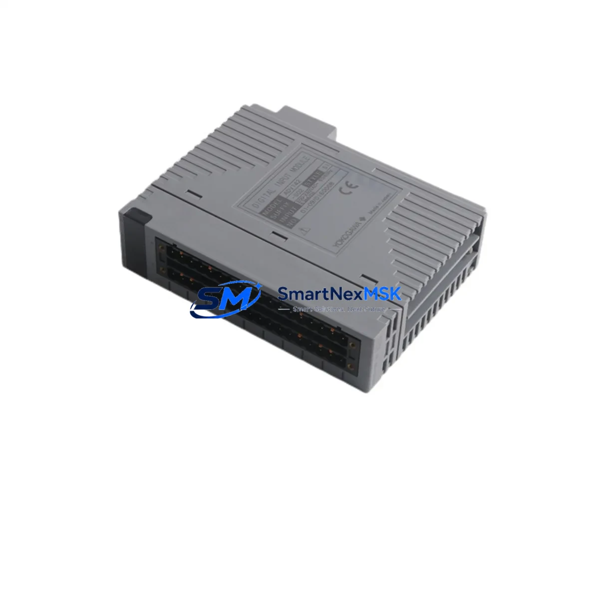
YOKOGAWA ADV142-S02 S1 Retrofit-Ready Digital Input Module for CENTUM VP & CS3000 Control Systems
The YOKOGAWA ADV142-S02 S1 is a 32-channel Digital Input Module engineered for seamless integration into CENTUM VP and CS3000 Distributed Control Systems. As legacy DCS installations age and OEM support windows close, plant engineers increasingly rely on verified retrofit-ready replacements to sustain production continuity without committing to full platform migrations. The ADV142-S02 S1 addresses exactly this need — delivering drop-in compatibility, verified I/O mapping, and a 12-month warranty backed by pre-shipment functional testing.
Whether you are replacing a failed module in an emergency shutdown scenario, upgrading a degraded I/O subsystem during a planned turnaround, or expanding digital input capacity on an existing CENTUM VP node, the ADV142-S02 S1 provides the electrical and logical compatibility required to restore or extend system operation with minimal engineering intervention.
Upgrade Compatibility Table
| Parameter | ADV142-S02 S1 Specification | Retrofit Notes |
|---|---|---|
| Compatible Platforms | CENTUM VP, CS3000 | Verify node address assignment in Engineering Workplace before installation |
| Channel Count | 32 Digital Input Channels | Confirm field wiring terminal block pitch matches existing ADV142 series layout |
| Input Signal Type | Dry contact / Voltage input (configurable) | Review existing I/O builder configuration; re-download after module swap if required |
| Backplane Interface | CENTUM VP / CS3000 standard I/O bus | Compatible with standard I/O nest; no adapter required for same-series replacement |
| Module Address | Configured via Engineering Workplace | Address must match original module slot assignment; verify before power-up |
| Communication Protocol | CENTUM internal V-net / Vnet/IP | No protocol migration required for same-generation replacement |
| Power Consumption | Refer to YOKOGAWA datasheet | Verify nest power budget; check ESB-50D or ESB-100D power supply capacity |
| Installation Method | Hot-swap capable (system-dependent) | Confirm hot-swap eligibility in system configuration; cold-swap recommended for first-time retrofit |
| Firmware / Revision | S1 hardware revision | Confirm revision compatibility with existing FCS firmware version in Engineering Workplace |
| Warranty | 12 Months | Covers manufacturing defects; pre-shipment functional test report available on request |
Retrofit Planning for Existing Automation Systems
A successful ADV142-S02 S1 retrofit begins well before the module arrives on site. Engineers should start by auditing the existing I/O nest configuration, confirming the slot position of the failed or aging module, and cross-referencing the nest’s power supply — typically an ESB-50D or ESB-100D power module — to ensure available capacity accommodates the replacement without triggering an overload condition on the I/O bus.
Terminal wiring is the next critical checkpoint. The ADV142-S02 S1 uses the standard CENTUM VP terminal block layout, but field wiring should be photographed and documented before disconnection. In older CS3000 installations, terminal blocks may have been modified or relabeled over years of maintenance cycles, making as-built documentation unreliable. A physical point-to-point check against the original I/O list is strongly recommended.
For systems running on CENTUM VP R5 or later, the Engineering Workplace software provides an I/O module replacement wizard that simplifies address reassignment and configuration download. Engineers working on older CS3000 nodes may need to use the legacy System View tool to re-register the module and push a revised I/O builder file to the Field Control Station (FCS). In either case, the FCS should be placed in manual control mode for all loops connected to the affected DI module before the swap is initiated.
Where the retrofit involves migrating from a discontinued ADV141 or ADV151 series module to the ADV142-S02 S1, additional steps are required. Channel mapping differences between module generations must be reconciled in the I/O builder, and any HMI faceplates or operator graphics in the CENTUM VP HIS (Human Interface Station) that reference specific channel tags should be reviewed for accuracy after the configuration download. YOKOGAWA’s FAST/TOOLS historian, if deployed, should also be checked to confirm that tag references remain intact following the module address update.
Communication link integrity is another area requiring attention in multi-node CENTUM VP architectures. The V-net or Vnet/IP backbone connecting FCS nodes to the HIS and Engineering Workplace should be verified as stable before and after the module swap. In plants where Vnet/IP has been introduced as part of a partial migration from the older V-net coaxial bus, the network switch configuration and VLAN assignments should be confirmed to ensure the replacement module’s node traffic is correctly routed.
For I/O expansion projects — rather than direct replacements — the ADV142-S02 S1 can be added to an available slot in an existing I/O nest, provided the nest’s ESB power budget and backplane slot count permit. In cases where the existing nest is fully populated, a supplementary I/O nest with an additional ESB-50D power module and the appropriate nest cable may be required. The ANB10D or ANB10S nest bus coupler is commonly used in these configurations to extend the I/O subsystem without modifying the FCS node address structure.
Programming cable access is also a practical consideration during retrofit commissioning. A YOKOGAWA-compatible RS-232 or USB programming cable connected to the Engineering Workplace workstation is required for configuration downloads. Ensure the workstation running Engineering Workplace has the correct FCS project file loaded and that the project revision matches the currently deployed FCS firmware before initiating any download sequence.
Downtime Control During System Migration
Minimizing unplanned downtime during a DI module retrofit requires a structured pre-execution plan. The most effective approach is to complete all configuration preparation — including I/O builder edits, address verification, and HMI tag review — in the Engineering Workplace offline environment before the maintenance window opens. This allows the on-site team to focus exclusively on physical installation and configuration download during the actual outage period.
Where process conditions permit, placing the affected control loops in manual mode at the FCS level — rather than at the HIS operator station — provides a more reliable control state during the swap. This ensures that even if the HIS loses communication with the FCS during the module replacement, the field devices remain in a defined, safe state rather than defaulting to an undefined output condition.
For critical loops where even brief interruption is unacceptable, a parallel wiring strategy can be employed: the replacement ADV142-S02 S1 is pre-wired in an adjacent slot or temporary nest, configured and verified offline, and then cut over by transferring field wiring in a single, rapid sequence. This approach is particularly effective in refinery and chemical plant environments where process continuity requirements are stringent.
After the module is installed and the configuration download is complete, a systematic channel-by-channel verification should be performed using the CENTUM VP diagnostic tools available in Engineering Workplace. Each DI channel should be exercised from the field — either by actuating the connected field device or by using a loop calibrator to simulate the input signal — and the corresponding tag value confirmed in the HIS display. This step protects against wiring errors and ensures that the restored I/O map accurately reflects the physical field installation before the loops are returned to automatic control.
All ADV142-S02 S1 units supplied by SMARTNEXMSK are subject to pre-shipment functional testing, and a test report is available upon request. The 12-month warranty covers manufacturing defects and provides a clear remediation path in the event of early-life failure, reducing the financial risk associated with retrofit procurement from the secondary market.
Retrofit Support FAQ
Q1: Is the ADV142-S02 S1 a direct drop-in replacement for the ADV142-S02 without the S1 suffix?
The S1 suffix denotes a hardware revision. In most CENTUM VP and CS3000 installations, the ADV142-S02 S1 is backward-compatible with the base ADV142-S02 slot and wiring configuration. However, firmware version compatibility should be confirmed in Engineering Workplace before installation, as some early CS3000 FCS firmware revisions may require a patch update to recognize the S1 hardware revision correctly.
Q2: What wiring changes are required when replacing an older ADV141 series module with the ADV142-S02 S1?
The ADV141 and ADV142 series use different terminal block configurations. A wiring adapter or re-termination at the field terminal block will be required. The I/O builder configuration must also be updated to reflect the new module type and channel mapping. SMARTNEXMSK recommends preparing a revised wiring schedule and I/O builder file before the maintenance window to minimize on-site engineering time.
Q3: Can the ADV142-S02 S1 be installed while the CENTUM VP system is running (hot-swap)?
Hot-swap capability depends on the specific FCS configuration and the CENTUM VP software revision in use. YOKOGAWA supports online module replacement in certain configurations, but this must be verified in the system’s Engineering Workplace project settings before attempting a live swap. For first-time retrofits or where system configuration is uncertain, a cold-swap during a planned shutdown is the recommended approach to avoid unintended process disturbances.
Q4: What does the 12-month warranty cover, and how is a warranty claim processed?
The 12-month warranty covers manufacturing defects identified under normal operating conditions consistent with YOKOGAWA’s published specifications for the ADV142-S02 S1. Pre-shipment functional test reports are available on request and document the module’s verified condition at the time of dispatch. To initiate a warranty claim, contact SMARTNEXMSK at sales@smartnexmsk.com with the order reference, module serial number, and a description of the observed fault. Replacement or repair will be coordinated based on fault diagnosis.
© 2026 SMARTNEXMSK. All rights reserved.
Original Source: https://smartnexmsk.com
Contact: sales@smartnexmsk.com | +86 18259474341


