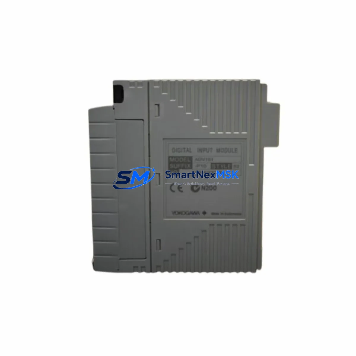
Yokogawa ADV151-P10 Maintenance-Ready Spare for CENTUM VP Automation
The Yokogawa ADV151-P10 is a digital output module designed for the CENTUM VP distributed control system — one of the most widely deployed DCS platforms in refining, petrochemical, power generation, and continuous process industries. As a maintenance-ready original spare, the ADV151-P10 supports rapid field replacement, minimizing unplanned downtime and protecting process continuity in critical automation environments.
For maintenance engineers managing aging CENTUM VP control cabinets, having a verified ADV151-P10 on the shelf is a fundamental risk-reduction strategy. This module interfaces directly with field devices through discrete output channels, controlling solenoid valves, motor starters, relay coils, and signal lamps. When a channel fails or the module degrades, the impact on process control can be immediate — making fast, compatible replacement essential.
Each unit supplied by SMARTNEXMSK is sourced as an original Yokogawa component, function-tested prior to shipment, and backed by a 12-month warranty. We maintain long-term stock of ADV151-P10 and related CENTUM VP I/O modules to support both emergency callouts and planned maintenance schedules.
Spare Maintenance Table
| Parameter | Specification |
|---|---|
| Part Number / SKU | ADV151-P10 |
| Brand | YOKOGAWA |
| Series / Platform | CENTUM VP DCS |
| Module Type | Digital Output Module |
| Output Channels | 16-point DO (transistor / relay, model-dependent) |
| Output Voltage Range | 24 VDC nominal field supply |
| Load Current per Channel | Up to 0.5 A per point (verify with system datasheet) |
| Isolation | Optical isolation between field and system bus |
| Backplane Interface | CENTUM VP I/O bus (node unit compatible) |
| Mounting | Hot-swap capable in CENTUM VP I/O nest |
| Operating Temperature | 0 °C to 55 °C |
| Humidity | 5% to 95% RH, non-condensing |
| Country of Origin | Japan |
| Compatibility | CENTUM VP R4.x / R5.x / R6.x field control stations |
| Replaces / Supersedes | ADV151 legacy variants (confirm revision with engineering) |
| Condition | Original, new or refurbished-to-spec |
| Pre-shipment Test | Function tested, channel-by-channel verification |
| Warranty | 12 Months from date of shipment |
| Lead Time | In stock — ships within 3–5 business days |
Maintenance Planning for Continuous Operation
When a CENTUM VP field control station requires ADV151-P10 replacement, experienced maintenance engineers know that the digital output module rarely fails in isolation. A thorough site inspection and cabinet audit should accompany any planned or emergency swap to prevent repeat failures and ensure system integrity.
Begin by verifying the 24 VDC field power supply feeding the DO module’s output commons. A degraded or undersized power supply — such as a Yokogawa PW481 or equivalent DIN-rail PSU — can cause intermittent channel faults that mimic module failure. Check output voltage under load and inspect for ripple or voltage sag before condemning the ADV151-P10.
Inspect the terminal block assemblies and field wiring connected to the module’s output terminals. Loose terminations, corroded contacts, or undersized conductors on solenoid valve or relay coil circuits are a common root cause of DO channel degradation. If the cabinet uses Yokogawa-compatible marshalling terminal strips or signal cable assemblies, verify continuity and insulation resistance on all active channels.
Review the status of associated digital input modules — such as the ADV151 DI counterpart or ADI series modules — that provide feedback confirmation for the outputs being controlled. A failed feedback DI channel can mask a healthy DO output, leading to unnecessary module replacement. Cross-check both sides of the I/O loop before pulling the ADV151-P10.
For cabinets with relay output expansion, inspect any interposing relay modules or relay terminal blocks wired downstream of the DO module. Relay coil burnout or contact welding can back-feed voltage into the DO channel and cause permanent damage. Replace suspect relays as part of the same maintenance event.
Check the CENTUM VP node unit (NUT) or field control unit (FCU) backplane for signs of corrosion, bent connector pins, or loose module seating. The ADV151-P10 relies on a clean backplane connection for both power and communication. A damaged I/O nest slot may cause the replacement module to report faults immediately after installation.
If the plant uses HART-enabled analog output modules (such as the AAV141 or AAV142) in the same control loop, verify that HART communication is intact and that the field device configuration has not been corrupted during the fault event. While the ADV151-P10 is a discrete output module, mixed I/O cabinets often share common power rails and grounding buses that affect all module types.
For systems with communication modules handling Modbus, PROFIBUS, or Foundation Fieldbus integration — such as the ALF111 or ACF11 series — confirm that the communication link to the affected field control station remains healthy after the module swap. A module replacement that triggers a node restart can temporarily disrupt fieldbus segments if not properly managed.
Finally, update the plant’s spare parts register to reflect the ADV151-P10 consumption and reorder point. Best practice for CENTUM VP installations is to maintain a minimum of one spare DO module per field control station, alongside spares for the power supply unit, CPU module, and at least one AI and AO module per station type.
Site Replacement Workflow
Step 1 — Pre-replacement verification: Confirm the ADV151-P10 part number and hardware revision against the installed module label and the CENTUM VP engineering database. Mismatched revisions can cause configuration download errors. Obtain a signed work permit and notify the control room operator before proceeding.
Step 2 — Safe state and output inhibit: Place all outputs controlled by the affected module into a safe state using the CENTUM VP HIS (Human Interface Station) operator console. Inhibit outputs where process safety permits. For critical outputs (e.g., ESD solenoids), coordinate with the safety system engineer before isolation.
Step 3 — Hot-swap extraction: The ADV151-P10 supports hot-swap replacement in a running CENTUM VP system without requiring a full station shutdown. Grasp the module handle firmly, release the locking lever, and extract the module smoothly. Avoid touching the backplane connector pins.
Step 4 — Module insertion and seating: Insert the replacement ADV151-P10 into the correct I/O nest slot, aligning the guide rails carefully. Press firmly until the locking lever engages. The CENTUM VP system will automatically detect the new module and begin configuration download within seconds.
Step 5 — Post-replacement functional test: From the HIS, force each output channel individually and verify field device response. Check the system alarm log for any residual faults. Confirm that all previously active outputs have returned to their correct states before releasing the loop to automatic control.
Step 6 — Documentation: Record the replacement in the plant maintenance management system (CMMS), including the removed module’s serial number, fault description, replacement date, and technician ID. Retain the faulty module for failure analysis if required by the plant’s reliability program.
Spare Parts Support FAQ
Q1: Is the ADV151-P10 compatible with all CENTUM VP revisions?
The ADV151-P10 is designed for the CENTUM VP platform and is generally compatible across R4.x, R5.x, and R6.x field control stations. However, hardware revision levels of the module itself may affect compatibility with specific FCU generations. Always cross-reference the module revision label against your CENTUM VP engineering documentation or contact our technical team with your FCU model number before ordering.
Q2: What testing is performed before shipment?
Every ADV151-P10 unit supplied by SMARTNEXMSK undergoes channel-by-channel functional verification prior to dispatch. We test output switching, isolation integrity, and backplane communication simulation where test fixtures permit. A test report is available upon request for critical plant applications.
Q3: How should the ADV151-P10 be stored as a long-term spare?
Store the module in its original anti-static packaging in a climate-controlled environment: 10 °C to 40 °C, relative humidity below 75% non-condensing, away from direct sunlight and electromagnetic interference sources. Inspect the module annually for connector oxidation and re-test if stored for more than 24 months before deployment.
Q4: What does the 12-month warranty cover?
The 12-month warranty covers manufacturing defects and functional failures under normal operating conditions from the date of shipment. It does not cover damage caused by incorrect installation, overvoltage events, physical impact, or use outside the module’s rated environmental specifications. Warranty claims are processed with return of the defective unit and a completed fault description form.
© 2026 SMARTNEXMSK. All rights reserved.
Original Source: https://smartnexmsk.com
Contact: sales@smartnexmsk.com | +86 18259474341


