YOKOGAWA ADV151-P53 S2 Maintenance-Ready Spare for CENTUM Automation
The YOKOGAWA ADV151-P53 S2 is a field-proven digital output (DO) module designed for continuous-duty service within the CENTUM VP and CENTUM CS 3000 distributed control systems. For maintenance engineers managing aging DCS infrastructure, this module represents a critical line item in any structured spare parts program. Unplanned failure of a DO module can immediately halt actuator commands — shutting down valves, contactors, motor starters, and interlock circuits — resulting in costly process downtime. Stocking a verified original ADV151-P53 S2 eliminates the diagnostic delay and sourcing lead time that typically extend emergency shutdowns from hours into days.
This unit ships as a tested, original YOKOGAWA spare with a 12-month warranty covering manufacturing defects and functional performance. Each module undergoes pre-shipment functional verification to confirm channel integrity, output signal accuracy, and backplane communication before dispatch. Whether you are executing a planned turnaround, responding to a fault alarm, or building a minimum viable spare parts inventory for a CENTUM-based control room, the ADV151-P53 S2 is a direct, plug-compatible replacement that requires no firmware reconfiguration when installed into a correctly configured FCS (Field Control Station).
Procurement engineers sourcing for multi-site operations will find long-term supply continuity a key advantage. YOKOGAWA’s ADV151 series modules have been deployed across refining, petrochemical, power generation, and pharmaceutical facilities globally. Maintaining at least one cold-standby unit per critical FCS cabinet is a widely adopted best practice in IEC 61511-aligned safety and reliability programs.
Spare Maintenance Table
| Parameter | Specification |
|---|---|
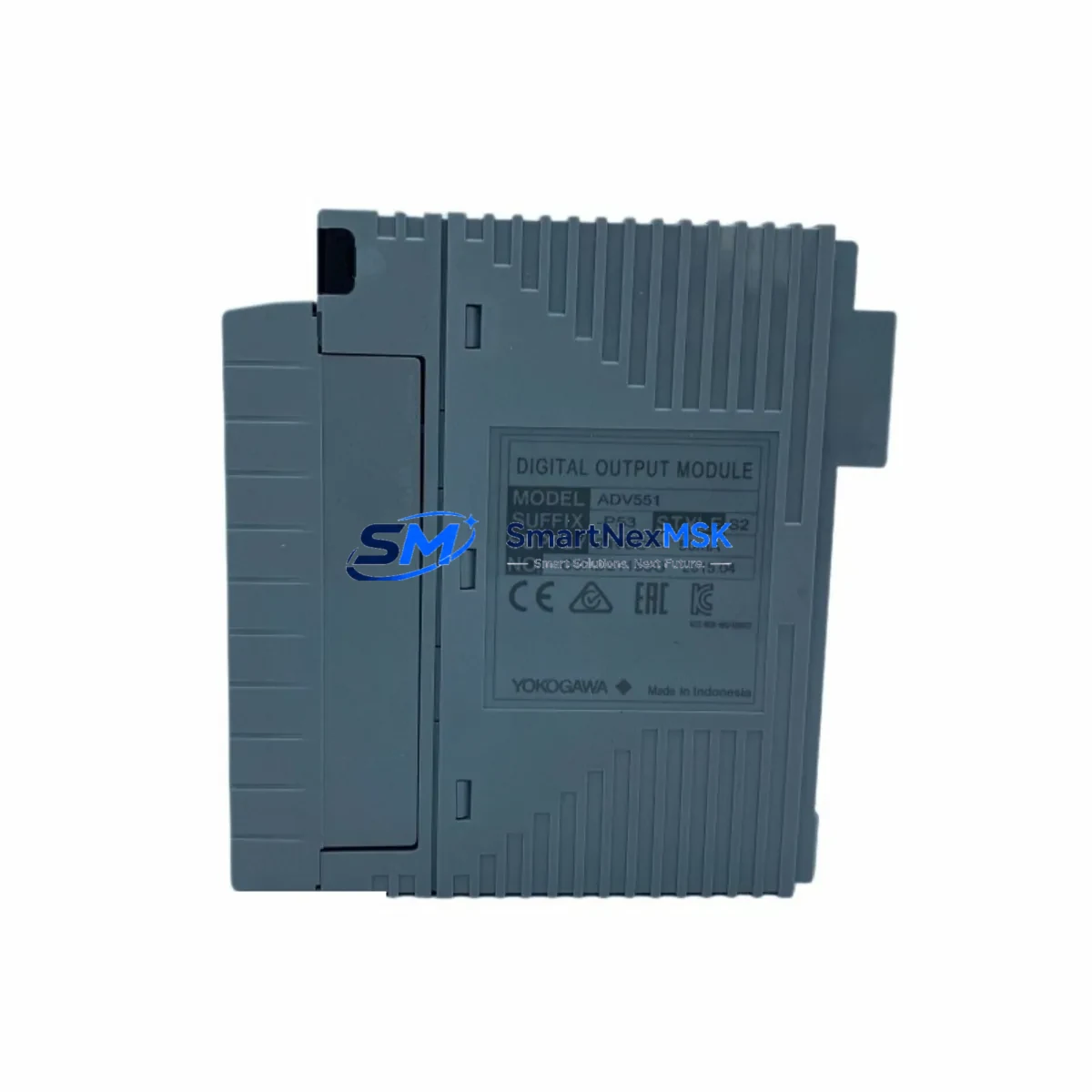
| Part Number | ADV151-P53 S2 |
| Brand | YOKOGAWA |
| Module Type | Digital Output (DO) Module |
| Compatible Systems | CENTUM VP, CENTUM CS 3000 |
| Series | ADV151 / Vnet/IP FCS I/O |
| Output Channels | 16-channel (typical for ADV151 series) |
| Output Signal Type | Transistor / Relay contact DO (per channel configuration) |
| Backplane Interface | CENTUM VP / CS 3000 I/O nest compatible |
| Operating Temperature | 0°C to 55°C (standard industrial environment) |
| Mounting | I/O nest slot insertion, tool-free hot-swap capable (with FCS support) |
| Country of Origin | Japan |
| Condition | Original, tested spare |
| Warranty | 12 months from shipment date |
| Maintenance Recommendation | Inspect output channel LEDs, verify terminal wiring, confirm FCS I/O map assignment during replacement |
Maintenance Planning for Continuous Operation
When a CENTUM VP or CS 3000 system flags a DO module fault — whether through a hardware alarm on the HIS (Human Interface Station) or a field device failing to respond to output commands — the replacement workflow must be fast and systematic. The ADV151-P53 S2 is rarely the only component that warrants inspection during a corrective maintenance event.
Maintenance engineers should simultaneously audit the associated ADV151 series analog output modules installed in the same I/O nest, as shared backplane power distribution can cause cascading faults. The AFV10D or AFV30D power supply modules feeding the FCS cabinet should be load-tested; a degraded power supply is a common root cause of intermittent DO module faults that are misdiagnosed as module failures. Inspect the terminal block assemblies and field wiring terminations at the I/O nest — corroded or loose terminals on 24 VDC output circuits are a frequent source of false channel-open alarms.
If the DO module drives motor starter or contactor circuits, the interposing relay modules (such as YOKOGAWA’s relay output accessories or equivalent DIN-rail mounted relay banks) should be tested for coil resistance and contact continuity. For systems where the ADV151-P53 S2 interfaces with safety interlock loops, verify that the associated signal isolators or galvanic separation barriers remain within calibration. Communication health between the FCS and the I/O nest should be confirmed via the Vnet/IP communication module status indicators — a degraded network node can produce phantom DO faults.
During planned shutdowns, it is also advisable to inspect the ESB bus coupler and I/O nest backplane connectors for oxidation, and to verify that the CENTUM VP engineering workstation (EWS) has a current backup of the FCS configuration database. This ensures that if a module swap triggers a re-download, the correct I/O tag assignments and interlock logic are restored without manual re-entry. Fuse holders and miniature circuit breakers (MCBs) protecting the 24 VDC field power rail should also be checked for correct rating and contact integrity as part of the same maintenance window.
Site Replacement Workflow
Replacing the ADV151-P53 S2 on a live CENTUM VP system follows a structured sequence to minimize process impact. First, confirm the fault is isolated to the specific module slot using the FCS diagnostic screen on the HIS — do not assume a field device failure is a module failure without verifying the I/O channel status in the system software. If the FCS supports online module replacement (hot-swap), notify the process operator and place the affected output channels in manual or safe-state hold before extraction.
Remove the faulty module by releasing the front-panel locking lever and sliding it clear of the I/O nest. Insert the replacement ADV151-P53 S2 firmly until the backplane connector seats fully — the status LED should illuminate within seconds as the FCS recognizes the new module. Confirm all output channel assignments are restored correctly in the FCS I/O map and verify field device response before returning channels to automatic control. Document the replacement in the site maintenance log with the module serial number, slot address, and date.
For systems running legacy CENTUM CS 3000 firmware, confirm the ADV151-P53 S2 hardware revision is compatible with the installed FCS software version before installation. This avoids the rare but disruptive scenario of a hardware-software mismatch that prevents the FCS from recognizing the new module. Sourcing from a supplier who provides pre-shipment testing documentation — including channel-level output verification — significantly reduces the risk of installing a non-functional spare during an emergency.
Spare Parts Support FAQ
Q1: What is the recommended spare parts holding strategy for the ADV151-P53 S2?
For facilities with more than four FCS cabinets using ADV151-series DO modules, a minimum of two cold-standby units is recommended. High-criticality processes — continuous reactors, compressor trains, or safety-instrumented systems — should maintain at least one unit per FCS as an on-site hot spare. Rotate stock every 36–48 months to prevent electrolytic capacitor aging in stored modules.
Q2: How is compatibility with CENTUM VP and CS 3000 verified before shipment?
Each ADV151-P53 S2 unit is functionally tested prior to dispatch. Compatibility is confirmed against the YOKOGAWA hardware revision matrix for CENTUM VP R6.x and CS 3000 R3.x environments. If your site runs a specific firmware revision, provide the FCS software version at the time of order so the correct hardware suffix can be confirmed.
Q3: Can the ADV151-P53 S2 replace earlier ADV151 suffix variants?
The S2 suffix denotes a specific hardware revision. In most CENTUM VP installations, S2 modules are backward-compatible with S1-configured I/O nests, but this should be verified against the site’s FCS hardware compatibility table in the YOKOGAWA engineering documentation. When in doubt, provide your FCS model and software revision for pre-sale compatibility confirmation.
Q4: What does the 12-month warranty cover?
The 12-month warranty covers manufacturing defects and functional failures under normal operating conditions. It does not cover damage resulting from incorrect installation, overvoltage events, or environmental exposure beyond the module’s rated operating range. Warranty claims are supported with the original shipment documentation and pre-shipment test report provided at the time of delivery.
© 2026 SMARTNEXMSK. All rights reserved.
Original Source: https://smartnexmsk.com
Contact: sales@smartnexmsk.com | +86 18259474341


