YOKOGAWA ADV169-P00 S1 Spare for CENTUM VP Automation: Spare Replacement & Industrial Downtime Risk Control
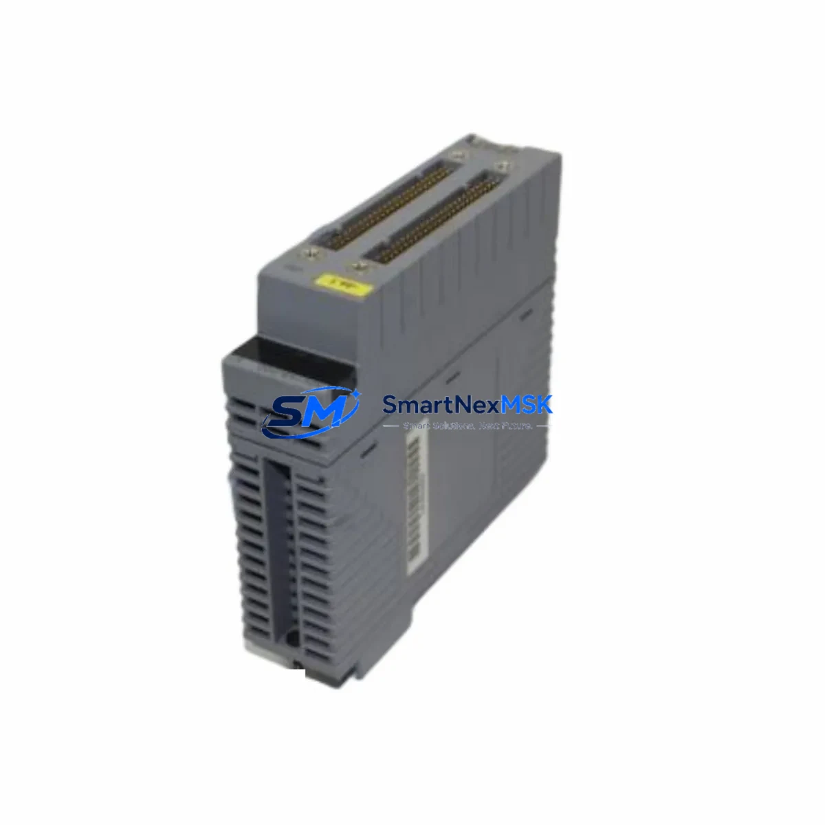
The YOKOGAWA ADV169-P00 S1 is an original digital input (DI) module designed for YOKOGAWA CENTUM VP and CS 3000 distributed control systems. As a field-proven I/O component in process automation environments — including petrochemical, power generation, pulp and paper, and pharmaceutical plants — this module plays a critical role in acquiring discrete on/off signals from field instruments, limit switches, motor status contacts, and safety interlock circuits. When this module fails or degrades, the consequences extend beyond a single I/O channel: entire control loops may go blind, operators lose visibility, and unplanned shutdowns become unavoidable.
Maintaining a verified, tested spare of the ADV169-P00 S1 in your on-site parts inventory is one of the most cost-effective strategies for protecting continuous operation. This listing provides an original, fully tested unit with a 12-month warranty, ready for immediate dispatch to minimize your mean time to repair (MTTR).
Spare Maintenance Table
| Parameter | Specification / Detail |
|---|---|
| Part Number / SKU | ADV169-P00 S1 |
| Manufacturer | YOKOGAWA Electric Corporation |
| Module Type | Digital Input (DI) Module |
| Compatible Systems | CENTUM VP, CENTUM CS 3000 |
| Series | CENTUM VP / CS 3000 I/O Series |
| Signal Type | Discrete Digital Input (dry contact / voltage input) |
| Mounting | DCS I/O backplane / node unit rack |
| Origin | Japan |
| Application Environment | Industrial process control, DCS field I/O nodes |
| Compatibility Confirmation | Verified against CENTUM VP and CS 3000 hardware configurations |
| Condition | Original, new or refurbished-to-spec; fully tested before shipment |
| Warranty | 12 Months from date of shipment |
| Maintenance Recommendation | Inspect signal wiring, terminal blocks, and backplane connector annually; replace if channel fault alarms persist after reset |
| Lead Time | In-stock units ship within 1–3 business days |
Maintenance Planning for Continuous Operation
When a maintenance or reliability engineer identifies a fault on the ADV169-P00 S1, the replacement procedure should not be treated in isolation. A DCS digital input module sits at the intersection of field wiring, power distribution, backplane communication, and controller logic — and a failure in any adjacent component can cause recurring faults even after the module is swapped.
Before or during replacement of the ADV169-P00 S1, a thorough site inspection should include the following associated components:
Power Supply Module (e.g., YOKOGAWA PW481 or equivalent node power unit): Verify that the node unit’s 24 VDC supply rail is within tolerance. An under-voltage condition on the power supply module is a common root cause of intermittent DI module faults and should be ruled out before condemning the ADV169-P00 S1.
I/O Node Unit / Backplane (e.g., ANB10D or ANB10S node units): Inspect the backplane slot for bent pins, oxidation, or contamination. A damaged backplane connector will cause the replacement ADV169-P00 S1 to report the same fault. Clean the slot contacts and verify seating torque per YOKOGAWA installation guidelines.
Field Terminal Assembly / Terminal Block (e.g., TB series terminal blocks): Check field wiring terminations at the associated terminal block. Loose screws, corroded terminals, or reversed polarity on dry-contact inputs are frequent causes of false DI channel alarms. Re-torque all terminals and verify continuity with a calibrated multimeter.
Signal Cables and Field Wiring: Inspect multi-pair signal cables running from the marshalling cabinet to the I/O node. Cable insulation breakdown, ground faults, or shield continuity issues can inject noise into digital input channels, causing erratic status readings that mimic module failure.
Relay Output Module (e.g., ADV151 or ADV161 series): If the ADV169-P00 S1 is used to monitor relay contact status in an interlock or motor control circuit, inspect the associated relay output module for contact wear or coil degradation. A relay that fails to fully open or close will produce ambiguous DI readings regardless of module condition.
Communication Module / ESB Bus Coupler (e.g., ACM12 or ACM22): Verify that the ESB (Extended Serial Backplane) bus coupler serving the affected node is communicating correctly with the field control unit (FCU). A degraded bus coupler can cause multiple I/O modules in the same node to report communication errors simultaneously.
Field Control Unit / FCU (e.g., AFV10D or AFV30D): Review the FCU’s diagnostic logs for any I/O scan errors or module health alarms that predate the ADV169-P00 S1 fault. Persistent FCU-level errors may indicate a systemic issue beyond a single module replacement.
Signal Isolator / Barrier (e.g., Zener barriers or galvanic isolators for IS zones): In hazardous area installations, verify that intrinsic safety barriers or galvanic isolators associated with the DI channels are within calibration and have not suffered surge damage. A failed isolator will block or distort the field signal before it reaches the ADV169-P00 S1.
Fuse / Circuit Protection: Check the field loop fuses or miniature circuit breakers (MCBs) in the marshalling cabinet. A blown fuse on a DI input loop will cause the channel to read permanently open, which is often misdiagnosed as a module fault.
Addressing these components as part of a structured replacement workflow — rather than a single module swap — significantly reduces the probability of repeat failures and unnecessary repeat downtime events.
Site Replacement Workflow
Step 1 — Pre-Replacement Verification: Confirm the exact part number ADV169-P00 S1 against the node unit label and the CENTUM VP hardware configuration tool (HIS engineering station). Do not substitute with ADV169-P00 without the S1 suffix unless confirmed compatible by YOKOGAWA documentation, as suffix variants may differ in channel count, isolation class, or firmware compatibility.
Step 2 — Safe State Confirmation: Place the affected I/O node in maintenance mode via the CENTUM VP HIS console. Verify that all field devices connected to the module’s DI channels are in a safe state or bypassed in the safety logic before proceeding. Document the bypass in the permit-to-work system.
Step 3 — Hot-Swap or Cold-Swap Assessment: CENTUM VP supports online module replacement (hot-swap) for most I/O modules. Confirm with your site’s YOKOGAWA system documentation whether the ADV169-P00 S1 slot supports hot-swap. If not, coordinate a brief controlled shutdown of the affected node to avoid data corruption on the FCU.
Step 4 — Physical Replacement: Remove the faulty module by releasing the front locking lever and sliding it out of the backplane slot. Insert the replacement ADV169-P00 S1 firmly until the connector seats fully and the locking lever engages. Do not force the module — misalignment will damage backplane pins.
Step 5 — Post-Replacement Functional Test: Return the node to normal operation via the HIS console. Verify that all DI channels on the replacement module report correct status by cross-checking against field device states. Confirm that no new alarms are generated and that the FCU diagnostic screen shows the module as healthy.
Step 6 — Documentation and Spare Replenishment: Record the replacement in the plant maintenance management system (CMMS) with the module serial number, fault description, and replacement date. Immediately initiate a purchase order for a new ADV169-P00 S1 spare to restore your on-site buffer stock. A minimum of one spare per active node type is the recommended baseline for CENTUM VP installations.
Spare Parts Support FAQ
Q1: Is the ADV169-P00 S1 compatible with both CENTUM VP and CS 3000 systems?
Yes. The ADV169-P00 S1 is designed for use within the CENTUM VP and CS 3000 I/O hardware families. However, compatibility depends on the specific node unit type and FCU firmware version in your installation. We recommend confirming the hardware revision against your YOKOGAWA system configuration report before ordering. Our technical team can assist with compatibility verification upon request.
Q2: What testing is performed before shipment?
Every ADV169-P00 S1 unit is functionally tested prior to dispatch. Testing includes power-on self-test verification, channel continuity checks, and backplane interface validation. Units that do not pass all test criteria are not shipped. A test record is available upon request for quality-critical procurement processes.
Q3: What does the 12-month warranty cover?
The 12-month warranty covers manufacturing defects and functional failures under normal operating conditions from the date of shipment. It does not cover damage resulting from incorrect installation, overvoltage events, physical impact, or use outside the module’s rated environmental specifications. Warranty claims are processed with a replacement unit dispatched after fault confirmation.
Q4: How should we manage long-term spare parts inventory for aging CENTUM VP systems?
For plants operating CENTUM VP or CS 3000 systems beyond their original design life, a structured lifecycle spare parts strategy is essential. We recommend maintaining a minimum of one ADV169-P00 S1 per active node type, with a review cycle aligned to your annual planned shutdown schedule. For systems approaching end-of-support milestones, consider increasing buffer stock to cover a 3–5 year horizon. We offer long-term supply agreements and reserved stock programs for high-criticality sites.
© 2026 SMARTNEXMSK. All rights reserved.
Original Source: https://smartnexmsk.com
Contact: sales@smartnexmsk.com | +86 18259474341


