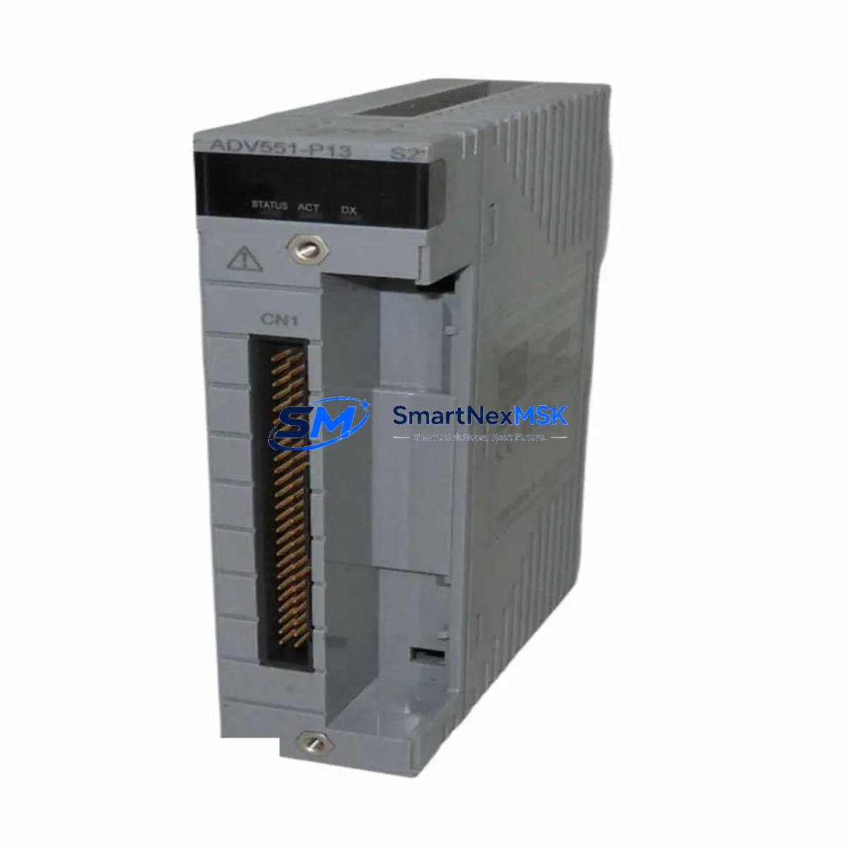
Yokogawa ADV551-P13 S2 Maintenance-Ready Spare for CENTUM VP Automation
Unplanned downtime in a CENTUM VP-based control system can cascade rapidly across an entire process unit. The Yokogawa ADV551-P13 S2 is a 32-channel digital output module designed for the CENTUM VP field control station (FCS), and its failure — or the absence of a verified replacement on the shelf — is one of the most common causes of extended outages in DCS-dependent facilities. Sourcing a tested, original ADV551-P13 S2 before a fault occurs is the single most effective step a maintenance team can take to protect process continuity.
This listing supplies the ADV551-P13 S2 as a maintenance-ready spare: inspected, function-tested, and shipped with documentation. Each unit is verified against Yokogawa CENTUM VP hardware compatibility requirements before dispatch and covered by a 12-month warranty from the date of delivery. Whether you are building a first-line spare inventory, replacing a failed module on an emergency basis, or retiring an older ADV551-P10 or ADV551-P11 variant from an aging FCS cabinet, this unit provides a direct, configuration-compatible replacement path.
Spare Maintenance Table
| Parameter | Specification |
|---|---|
| Part Number / SKU | ADV551-P13 S2 |
| Manufacturer | Yokogawa Electric Corporation |
| Series / Platform | CENTUM VP Field Control Station (FCS) |
| Module Type | Digital Output (DO) Module |
| Output Channels | 32 channels (contact output) |
| Output Type | Relay / Transistor contact (per channel configuration) |
| Rated Voltage | 24 VDC (field side); isolated per channel group |
| Installation | Hot-swap capable; slide-in module for CENTUM VP I/O nest |
| Communication | Internal V-net / ESB bus via FCS backplane |
| Compatible FCS | CENTUM VP FCS (AFC30D, AFC30S and compatible variants) |
| Operating Temperature | 0 °C to 55 °C (standard industrial environment) |
| Origin | Japan |
| Condition | Original Yokogawa; function-tested before shipment |
| Warranty | 12 months from delivery date |
| Maintenance Recommendation | Inspect terminal block wiring, verify DO channel diagnostics in CENTUM VP HIS, confirm field device continuity before hot-swap |
Maintenance Planning for Continuous Operation
A digital output module like the ADV551-P13 S2 sits at the intersection of the control system and the field — it drives solenoid valves, motor starters, alarm annunciators, and interlock relays. When planning a replacement or a scheduled inspection, maintenance engineers should treat the module not in isolation but as part of a broader I/O and power distribution circuit.
Before or during an ADV551-P13 S2 swap, the following components in the same FCS cabinet and field loop should be inspected or staged as secondary spares:
- ADV151-P13 / ADV161-P13 Digital Input Modules — paired DI modules in the same I/O nest often share the same terminal block wiring harness and field cable runs; a wiring fault that damages a DO module may have already stressed the adjacent DI module.
- AAV141 / AAV142 Analog Output Modules — if the control loop includes both discrete and analog outputs to the same field device (e.g., a control valve with a positioner and a solenoid), verify the analog output module is functioning correctly before returning the loop to service.
- AIP829 / AIP835 Power Supply Modules — the FCS I/O nest is powered by dedicated Yokogawa power supply modules; a degraded power supply is a common root cause of intermittent DO channel faults and should be load-tested during any unplanned module replacement.
- Terminal Block Assemblies (TB series) — the field-side terminal blocks connecting the ADV551-P13 S2 to field wiring should be inspected for loose screws, corrosion, and insulation breakdown, particularly in high-vibration or high-humidity environments.
- ESB Bus Cables and Backplane Connectors — the internal ESB bus that carries I/O data between the FCS processor and the I/O modules can develop intermittent faults at the backplane connector; clean and reseat connectors during any module pull.
- ACM12 / ACM22 Communication Modules — if the FCS communicates with a redundant control network or a Vnet/IP segment, verify the communication module status in CENTUM VP HIS after any I/O module replacement to confirm no bus errors were introduced.
- Interposing Relay Modules — many CENTUM VP installations use interposing relay panels between the ADV551-P13 S2 outputs and high-current field loads; relay coil resistance and contact condition should be checked as part of the same maintenance event.
- CENTUM VP HIS (Human Interface Station) — after module replacement, confirm that all 32 DO channels are correctly mapped in the HIS faceplate, that no IOM (I/O Module) alarm is active, and that the module status tag reads NORMAL before releasing the loop to automatic control.
- Signal Isolators and Surge Protectors — field cables entering the control cabinet from outdoor or long-run installations should be protected by surge arrestors; inspect these devices for evidence of discharge events that may have contributed to the module failure.
Maintaining a minimum of one ADV551-P13 S2 spare per FCS cabinet — alongside one spare power supply module and one spare DI module of the same channel density — is the recommended inventory posture for facilities operating CENTUM VP systems beyond their original design life.
Site Replacement Workflow
The ADV551-P13 S2 supports hot-swap replacement within the CENTUM VP architecture, which significantly reduces the downtime window compared to older CENTUM CS 3000 or CENTUM CS 1000 platforms. However, a structured replacement workflow is essential to avoid introducing new faults during the swap.
Step 1 — Pre-replacement verification: In CENTUM VP HIS, navigate to the IOM status display for the target FCS. Confirm which DO channels are in fault and which are still operational. Place all affected field devices in manual or safe-state before proceeding.
Step 2 — Field isolation: De-energize the field-side terminal block for the ADV551-P13 S2 using the local isolation switch or by opening the field circuit breaker. Do not rely solely on the module’s internal channel disable function for field isolation.
Step 3 — Module extraction: Release the module locking lever, slide the ADV551-P13 S2 out of the I/O nest, and inspect the backplane connector for bent pins or contamination. Insert the replacement module and confirm the locking lever engages fully.
Step 4 — Post-replacement diagnostics: Re-energize the field-side terminal block. In CENTUM VP HIS, confirm the IOM status changes from FAULT to NORMAL within the expected initialization period (typically 30–60 seconds). Verify all 32 DO channels report correct status.
Step 5 — Loop return to service: Return field devices to automatic control one loop at a time, confirming correct output response at the field device before proceeding to the next loop. Document the replacement in the site maintenance management system (CMMS).
For facilities migrating from older ADV551-P10 or ADV551-P11 variants, the ADV551-P13 S2 is a direct slot-compatible replacement with no firmware reconfiguration required in standard CENTUM VP FCS configurations. This compatibility makes it the preferred long-term spare for mixed-vintage CENTUM VP installations.
Spare Parts Support FAQ
Q1: Is the ADV551-P13 S2 compatible with both CENTUM VP R4 and R6 field control stations?
Yes. The ADV551-P13 S2 is compatible across CENTUM VP FCS generations including R4, R5, and R6 variants. The module communicates via the ESB bus, which is consistent across these releases. Always confirm the specific FCS model and software revision with your site documentation before installation, as custom I/O mapping configurations may require verification in the CENTUM VP builder tool.
Q2: What pre-shipment testing is performed on each ADV551-P13 S2 unit?
Each unit undergoes functional channel testing to verify that all 32 DO channels respond correctly to command signals, that the module initializes without fault codes, and that the backplane connector meets contact resistance specifications. Units that do not pass all test criteria are not shipped. A test record is available upon request for quality-critical applications.
Q3: How should the ADV551-P13 S2 be stored if purchased as a long-term shelf spare?
Store the module in its original anti-static packaging in a dry, temperature-controlled environment (10 °C to 40 °C, relative humidity below 75% non-condensing). Avoid storage near strong magnetic fields or sources of electrostatic discharge. For shelf spares held longer than 24 months, a functional power-on test is recommended before deployment to confirm module health.
Q4: What does the 12-month warranty cover, and what is the return process?
The 12-month warranty covers manufacturing defects and functional failures under normal operating conditions from the date of delivery. It does not cover damage resulting from incorrect installation, overvoltage events, or physical mishandling. To initiate a warranty claim, contact sales@smartnexmsk.com with the order reference, a description of the fault, and the site installation date. Replacement or repair will be arranged within the agreed lead time.
© 2026 SMARTNEXMSK. All rights reserved.
Original Source: https://smartnexmsk.com
Contact: sales@smartnexmsk.com | +86 18259474341


