Yokogawa ADV551-P60 S2 Maintenance-Ready Spare for CENTUM Automation
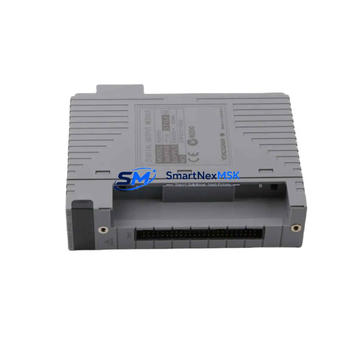
The Yokogawa ADV551-P60 S2 is a 32-channel transistor digital output module designed for the CENTUM VP and CENTUM CS 3000 distributed control systems. As a critical field I/O component, this module drives solenoid valves, motor starters, relay coils, and indicator lamps across process automation installations in oil & gas, petrochemical, power generation, and continuous manufacturing environments. When an ADV551-P60 S2 fails or degrades, the downstream impact is immediate: loss of discrete output control, unplanned process shutdown, and extended recovery time if a verified spare is not on hand. Sourcing a tested, original replacement unit from a reliable supplier is the fastest path to restoring normal operation.
This listing supplies the ADV551-P60 S2 as a maintenance-ready spare — inspected, function-tested, and shipped with a 12-month warranty. Each unit is verified against Yokogawa’s published electrical specifications before dispatch, ensuring that the module you receive is ready for direct installation without additional bench testing on site.
Spare Maintenance Table
| Parameter | Specification |
|---|---|
| Model | ADV551-P60 S2 |
| Brand | Yokogawa Electric Corporation |
| Module Type | 32-Channel Transistor Digital Output (DO) |
| Compatible Systems | CENTUM VP, CENTUM CS 3000 |
| Output Voltage Range | 12–24 V DC (field side) |
| Output Current per Channel | 0.5 A max |
| Isolation | Optical isolation, field side from system bus |
| Connector Type | P60 — 60-pin field terminal connector |
| Mounting | Node Unit / Field Control Unit (FCU) backplane slot |
| Operating Temperature | 0 °C to 55 °C |
| Relative Humidity | 10–90% RH, non-condensing |
| Origin | Japan |
| Condition | Original, tested, maintenance-ready |
| Warranty | 12 months from date of shipment |
| Compatibility Note | Verify FCU firmware revision and node address assignment before installation |
| Maintenance Recommendation | Inspect P60 connector pins and field wiring terminal block at each planned outage; replace module if channel fault LED persists after power cycle |
Maintenance Planning for Continuous Operation
Replacing an ADV551-P60 S2 in a live CENTUM VP or CS 3000 system is rarely an isolated task. Maintenance engineers who have performed this replacement in the field consistently report that adjacent components in the same control cabinet and field loop should be inspected simultaneously to prevent repeat callouts within the same maintenance window.
Begin with the P60 field terminal block (Yokogawa TBX series or equivalent) that mates with the module connector. Corroded or loose terminals are a common root cause of intermittent channel faults that are incorrectly attributed to the DO module itself. While the cabinet is open, inspect the 24 V DC field power supply feeding the output loop — a degraded power supply with marginal voltage regulation will cause transistor output channels to behave erratically even after a new module is installed. If the installation uses a redundant power supply pair such as the Yokogawa PW481 or equivalent DIN-rail PSU, verify that both units are sharing load correctly and that the diode ORing module shows no fault indication.
For nodes that combine digital output with digital input functions, check the companion ADV151 or ADV161 digital input module in the same node unit. Input modules in the same FCU share the system bus and a fault on one module can generate misleading diagnostics on adjacent slots. Similarly, if the process loop includes relay output modules such as the ADV561 for higher-current switching duties, inspect relay contact condition and coil drive voltage at the same time.
Communication integrity between the FCU and the HIS (Human Interface Station) depends on the ESB bus coupler or Vnet/IP network interface card installed in the field control unit. A marginal bus coupler can cause sporadic module communication errors that mimic hardware failure. Confirm that the FCU node unit backplane shows no bent or oxidized bus connector pins before seating the replacement ADV551-P60 S2.
Where the DO module drives solenoid valves through intrinsic safety barriers or galvanic isolators (such as MTL or P+F signal isolators), verify that the isolator output current capacity matches the new module’s drive capability. Aging isolators with reduced output current will prevent the solenoid from achieving full stroke even with a fully functional DO module. Finally, check the field junction box terminal strips and cable gland seals for moisture ingress, particularly in outdoor or high-humidity installations, as water in the field cable can cause leakage current that triggers false output states.
Maintaining a minimum stock of one ADV551-P60 S2 per FCU node, alongside a spare P60 terminal block and a spare 24 V field power supply module, is the recommended inventory posture for facilities operating CENTUM VP or CS 3000 systems beyond their original design life.
Site Replacement Workflow
Step 1 — Pre-replacement verification: Confirm the fault using the CENTUM VP System View or CS 3000 HIS alarm summary. Note the node address, slot number, and channel fault map before touching hardware. Download or print the current I/O assignment list for the affected node.
Step 2 — Safe state and permit: Place all output channels in the affected module to a safe de-energized state via the HIS or through field manual overrides. Obtain a Permit to Work and confirm with the process operator that the associated field devices (valves, motors) are in a safe position.
Step 3 — Module removal: With field power isolated to the P60 terminal block, release the module locking lever and withdraw the ADV551-P60 S2 from its backplane slot. Do not disconnect the P60 terminal block from the field wiring — the terminal block remains in place and the module unplugs from it.
Step 4 — Replacement installation: Insert the new ADV551-P60 S2 into the same slot. The module is keyed and will only seat correctly in the correct orientation. Engage the locking lever. Restore field power to the terminal block.
Step 5 — Online verification: From the HIS, confirm that the module status returns to normal (green) and that all 32 channels report correct state. Perform a channel-by-channel output test for any channels that were previously faulted. Document the replacement in the maintenance management system with the module serial number and date.
This workflow applies equally to planned maintenance replacements during scheduled outages and to emergency replacements during unplanned downtime. The ADV551-P60 S2 supports hot-swap in CENTUM VP systems with the appropriate FCU configuration — confirm this capability with your system documentation before attempting online replacement.
Spare Parts Support FAQ
Q1: Is this ADV551-P60 S2 an original Yokogawa module or a third-party compatible?
This is an original Yokogawa ADV551-P60 S2 module. We do not supply clones, refurbished-as-new, or third-party compatible substitutes. Each unit is sourced from verified supply channels and carries a 12-month warranty covering manufacturing defects and functional failure under normal operating conditions.
Q2: How do I confirm compatibility with my specific CENTUM VP or CS 3000 system revision?
The ADV551-P60 S2 is compatible with CENTUM VP R5.x and later, and with CENTUM CS 3000 R3.x systems. Compatibility depends on the FCU type (AFV10S, AFV30S, or equivalent) and the node unit generation. Provide your FCU model number and system revision when placing your order and our technical team will confirm compatibility before shipment.
Q3: What pre-shipment testing is performed on each module?
Each ADV551-P60 S2 is powered up and subjected to a full 32-channel output function test. Channel isolation, output voltage levels, and LED status indicators are verified. Modules that do not pass all test criteria are not shipped. A test record is available on request.
Q4: What is the lead time and what does the 12-month warranty cover?
In-stock units ship within 1–3 business days. The 12-month warranty covers functional failure of the module under normal operating conditions. It does not cover damage caused by incorrect installation, overvoltage, reverse polarity, or physical impact. Warranty claims are handled by return shipment — we ship a replacement unit upon receipt and inspection of the returned module.
© 2026 SMARTNEXMSK. All rights reserved.
Original Source: https://smartnexmsk.com
Contact: sales@smartnexmsk.com | +86 18259474341


