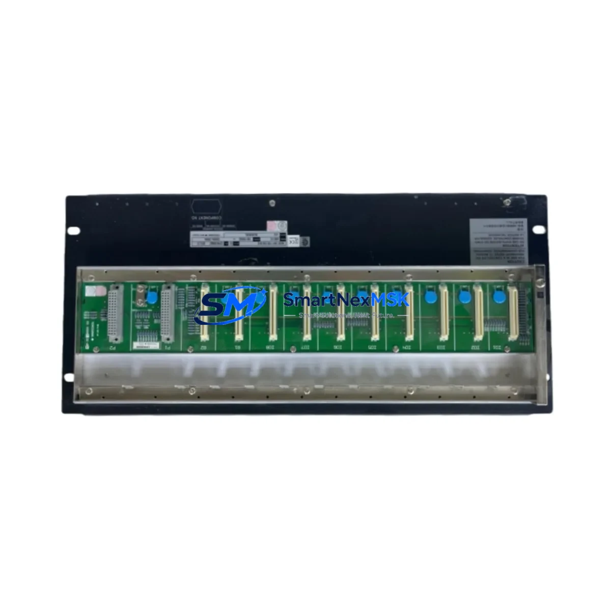
Yokogawa ANB10D-415/CU2T Maintenance-Ready Spare for CENTUM VP Automation
The Yokogawa ANB10D-415/CU2T is an original ESB (Enhanced Serial Backplane) Node Unit designed for the CENTUM VP Distributed Control System platform. As a critical communication and I/O coordination component within the field control station, this module plays a central role in maintaining uninterrupted process automation across refining, petrochemical, power generation, and continuous manufacturing environments. Sourced as a genuine original spare, the ANB10D-415/CU2T is tested before shipment and backed by a 12-month warranty, making it a reliable choice for both planned maintenance and emergency replacement scenarios.
Maintenance engineers managing CENTUM VP installations understand that ESB Node Unit failures can cascade rapidly — disrupting I/O communication between the field control station and connected I/O modules, triggering process alarms, and in worst cases, forcing unplanned shutdowns. Stocking the ANB10D-415/CU2T as a ready spare eliminates the lead-time risk associated with sourcing critical DCS components under emergency conditions. Procurement engineers are advised to treat this module as a Tier-1 spare: one unit per active field control station, with a secondary unit held at the central maintenance warehouse.
When replacing the ANB10D-415/CU2T during a scheduled outage or emergency callout, a thorough inspection of the surrounding control cabinet is strongly recommended. The ESB backplane and its associated node units operate in close electrical proximity to several interdependent components. Maintenance teams should simultaneously inspect the ANB10D-415/CU2T‘s paired power supply module — typically an AWB10D or equivalent CENTUM VP-compatible redundant power unit — to confirm stable DC rail voltage before reinserting the replacement node. Loose or corroded terminal connections on the ESB bus connector can cause intermittent communication faults that mimic node unit failure; these should be cleaned and re-torqued during the same maintenance window.
Spare Maintenance Table
| Parameter | Specification / Recommendation |
|---|---|
| Part Number | ANB10D-415/CU2T |
| Brand | Yokogawa Electric Corporation |
| Series / Platform | CENTUM VP (also compatible with CENTUM CS 3000 ESB architecture) |
| Module Type | ESB Node Unit (Enhanced Serial Backplane Node) |
| Product Type | DCS Node Unit |
| Origin | Japan |
| Typical Supply Voltage | 24 V DC (from dedicated DCS power supply rail) |
| Communication Interface | ESB Bus (Enhanced Serial Backplane) |
| Installation Environment | Control cabinet / field control station enclosure; IP20 or better |
| Operating Temperature | 0 °C to 55 °C (standard DCS cabinet conditions) |
| Compatibility | CENTUM VP FCS, CENTUM CS 3000 ESB-based field control stations |
| Maintenance Interval | Inspect annually; replace on fault indication or communication error |
| Pre-shipment Testing | Functional test performed before dispatch |
| Warranty | 12 Months from date of shipment |
| Condition | Original / Genuine Yokogawa spare |
Maintenance Planning for Continuous Operation
A structured spare parts strategy for CENTUM VP installations should extend beyond the ANB10D-415/CU2T node unit itself. During any planned inspection or corrective maintenance event involving this module, experienced field engineers recommend a concurrent review of the following components within the same field control station or control cabinet:
- ESB Coupler Module (e.g., ACB10D series) — The ESB coupler bridges the node unit to the I/O bus; a degraded coupler can cause the same communication faults as a failed node unit and should be tested in parallel.
- I/O Module Cards (e.g., AAI141, AAI543, ADV151) — Analog input/output modules connected via the ESB bus should be inspected for channel drift, blown fuses, or terminal corrosion whenever the node unit is replaced.
- Redundant Power Supply Units (AWB10D / AWB20D) — Confirm both primary and redundant power rails are within specification. A marginal power supply is a common root cause of intermittent node unit faults.
- Terminal Blocks and Field Wiring Connectors — Inspect all I/O terminal blocks for loose screws, oxidation, or moisture ingress. Re-torque to manufacturer specification.
- Communication Bus Cables and ESB Backplane Connectors — Inspect the ESB backplane ribbon or bus connector for bent pins, contamination, or mechanical stress. Replace if any physical damage is observed.
- Fuse Holders and Circuit Protection (e.g., 2A / 4A DIN-rail fuses) — Verify all field circuit fuses are intact and within rated current. Blown fuses on I/O channels are frequently overlooked during node unit replacement.
- Signal Isolators and Barriers (e.g., Yokogawa MTL or equivalent) — For installations in hazardous areas, confirm that Zener barriers or galvanic isolators in the same loop are functioning correctly and have not been damaged by the fault event.
- HMI Communication Link and VNET/IP Network Switch — After node unit replacement, verify that the CENTUM VP HMI workstation re-establishes communication with the field control station without residual alarms. Check the VNET/IP or V-net network switch port status if communication does not recover automatically.
- Battery Backup Unit (if installed) — Some CENTUM VP FCS configurations include a battery-backed memory module. Confirm battery health and replace if the backup duration has degraded below the minimum threshold.
Maintaining a documented spare parts list that covers these interdependent components — rather than stocking only the node unit in isolation — significantly reduces mean time to repair (MTTR) and supports a proactive maintenance culture aligned with IEC 61511 functional safety requirements.
Site Replacement Workflow
Replacing the ANB10D-415/CU2T in a live CENTUM VP installation follows a structured sequence to minimize process disruption and ensure system integrity:
- Pre-replacement verification: Confirm the replacement unit’s part number and firmware revision match the installed unit. Cross-reference the CENTUM VP engineering database to verify node address assignment and I/O module configuration.
- Process handover: Coordinate with the control room operator to place affected control loops in manual mode or transfer to redundant control paths before isolating the faulty node unit.
- Safe isolation: De-energize the field control station slot following the site’s lockout/tagout (LOTO) procedure. Discharge any residual bus voltage before handling the module.
- Physical replacement: Remove the faulty ANB10D-415/CU2T by releasing the module locking lever. Insert the replacement unit firmly until the bus connector seats fully. Secure the locking lever.
- Power-up and self-test: Re-energize the slot and observe the module’s LED status indicators. A solid green RUN LED confirms successful initialization. A flashing or red LED indicates a configuration mismatch or hardware fault.
- Communication verification: From the CENTUM VP engineering workstation, confirm that all I/O modules on the replaced node’s ESB segment are communicating normally. Clear any residual fault alarms.
- Loop testing: Perform a functional check on a representative sample of I/O channels to confirm signal integrity before returning control loops to automatic mode.
- Documentation: Record the replacement in the site maintenance management system (CMMS), including the removed module’s serial number, fault symptom, and replacement date.
This workflow applies equally to legacy CENTUM CS 3000 installations where ESB-compatible node units are being used to extend system life beyond the original platform’s end-of-support date — a common scenario in brownfield plants where full DCS migration is deferred.
Spare Parts Support FAQ
Q1: Is the ANB10D-415/CU2T compatible with both CENTUM VP and CENTUM CS 3000 systems?
The ANB10D-415/CU2T is designed for the CENTUM VP ESB architecture. Compatibility with CENTUM CS 3000 depends on the specific ESB bus revision and firmware version of the target field control station. We recommend confirming the installed FCS model and ESB generation with your Yokogawa system documentation before ordering. Our technical team can assist with compatibility verification prior to shipment.
Q2: What pre-shipment testing is performed on this spare unit?
Each ANB10D-415/CU2T unit undergoes functional testing before dispatch to verify power-up behavior, bus communication initialization, and LED status indication. Units that do not pass functional verification are not shipped. A test report is available upon request for quality-critical procurement processes.
Q3: How should this spare be stored if not immediately installed?
Store the ANB10D-415/CU2T in its original anti-static packaging in a dry, temperature-controlled environment (10 °C to 40 °C, relative humidity below 75% non-condensing). Avoid storing near strong electromagnetic fields or in environments with airborne contaminants. Inspect the module annually if held in long-term storage and re-test before installation if stored for more than 24 months.
Q4: What does the 12-month warranty cover?
The 12-month warranty covers manufacturing defects and functional failures under normal operating conditions from the date of shipment. It does not cover damage resulting from incorrect installation, overvoltage events, physical impact, or use outside the module’s rated environmental specifications. Warranty claims are supported by our technical team with a target response time of one business day.
© 2026 SMARTNEXMSK. All rights reserved.
Original Source: https://smartnexmsk.com
Contact: sales@smartnexmsk.com | +86 18259474341


