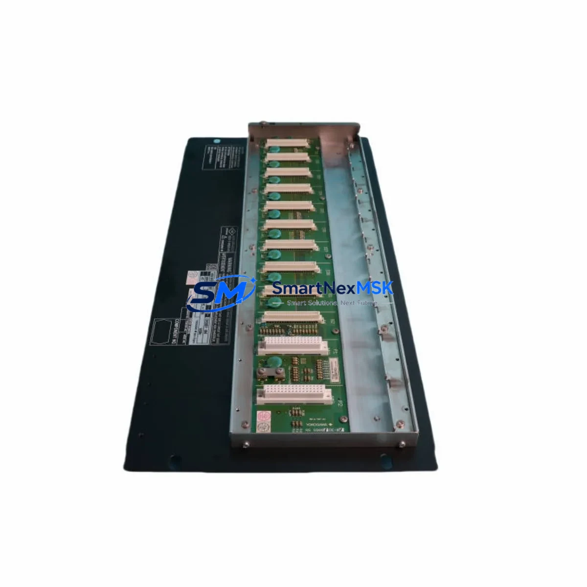
Yokogawa ANB10D-421-S1 Retrofit-Ready ESB Bus Node for CENTUM CS/VP Control Systems
The Yokogawa ANB10D-421-S1 is a field-proven ESB (Enhanced Signal Bus) Bus Node Module designed for integration within the CENTUM CS and CENTUM VP Distributed Control System platforms. As legacy CENTUM CS installations approach end-of-life and plant operators accelerate migration to CENTUM VP or CENTUM VP R6, the ANB10D-421-S1 remains a critical bridging component — enabling smooth, low-risk retrofits without requiring full cabinet redesigns or controller replacements.
SMARTNEXMSK maintains verified stock of the ANB10D-421-S1, sourced from decommissioned systems and authorized surplus channels. Every unit undergoes functional testing prior to shipment, with a 12-month warranty covering operational defects under normal industrial service conditions. Fast global shipping is available from our warehouse, with typical lead times of 3–7 business days for in-stock units.
Upgrade Compatibility Table
| Parameter | ANB10D-421-S1 Specification | Retrofit Notes |
|---|---|---|
| Compatible Platform | CENTUM CS, CENTUM VP, CENTUM VP R6 | Verify firmware revision of host FCS/LFCS before installation |
| Bus Interface | ESB (Enhanced Signal Bus) | Confirm ESB segment address does not conflict with existing nodes |
| Installation Type | Rack-mount, standard Yokogawa node slot | Compatible with ANB10D series rack positions; no mechanical modification required |
| Power Supply Requirement | 24 VDC (from rack power bus) | Verify rack PSU capacity — add PWR18D or equivalent if margin is insufficient |
| Communication Compatibility | ESB protocol, Vnet/IP compatible upstream | Upstream Vnet/IP switch (e.g., BCV1D) must support node count after addition |
| Replacement Candidates | ANB10D-421, ANB10D-421-S0 | S1 suffix denotes enhanced surge protection; direct drop-in for S0 variant |
| Commissioning Requirement | Node address configuration via CENTUM Engineering Environment | Backup existing node configuration before removal; restore after installation |
| Warranty | 12 Months | Covers operational defects; excludes physical damage from incorrect installation |
Retrofit Planning for Existing Automation Systems
Successful integration of the ANB10D-421-S1 into an aging CENTUM CS or CENTUM VP system requires a structured pre-retrofit assessment. Engineers should begin by auditing the existing ESB segment topology — documenting all active bus nodes, their assigned addresses, and the current load on each rack’s power supply. In many legacy installations, the PWR18D power supply module is operating near its rated capacity, and adding a new bus node without first verifying headroom can cause intermittent resets across the entire I/O subsystem.
Terminal wiring compatibility is the next critical checkpoint. The ANB10D-421-S1 uses the standard Yokogawa ESB connector pinout, but field wiring routed to older AAI141-S00 analog input modules or AAI841-S00 analog output modules must be inspected for insulation integrity and correct shielding before the new node is energized. In systems where the original wiring was installed more than ten years ago, partial rewiring of the I/O marshalling cabinet is often necessary to meet current EMC standards.
For plants running CENTUM CS with an older FCS (Field Control Station) such as the FFCS-V or LFCS2, the engineering team must confirm that the station’s software revision supports the ANB10D-421-S1’s enhanced diagnostic registers. If the FCS firmware is below the minimum supported revision, a coordinated firmware update — planned during a scheduled maintenance window — should precede the hardware swap. The CENTUM Engineering Environment (CAMS for HIS) provides the necessary tools to export the current control database, validate module assignments, and re-download the configuration after the new node is seated.
HMI screen updates are frequently overlooked during bus node replacements. If the replaced node previously hosted I/O points that are referenced in CENTUM HIS (Human Interface Station) graphic displays, operators must update the tag assignments in the HIS builder to reflect the new node address. Failure to do so results in stale or missing readings on the operator console, which can trigger nuisance alarms during the first hours of post-retrofit operation.
Communication link integrity should be verified end-to-end after installation. The ESB segment connecting the ANB10D-421-S1 to the upstream Vnet/IP network — typically routed through a BCV1D bus converter or equivalent — must be tested for signal quality using the built-in loopback diagnostics available in the CENTUM system status monitor. Any degradation in link quality at this stage is usually attributable to connector seating issues or cable routing near high-voltage conductors in the control cabinet.
For I/O expansion projects where the ANB10D-421-S1 is being added to an existing rack alongside modules such as the ADV151-P00 digital input module or the ADV551-P00 digital output module, the rack backplane slot assignments must be planned in advance using the CENTUM hardware configuration tool. Slot conflicts — particularly in mixed-generation racks where older S-series modules share space with newer P-series modules — are a common source of commissioning delays that can be entirely avoided with proper pre-planning.
Downtime Control During System Migration
Minimizing unplanned downtime during a bus node replacement is the primary concern for most plant engineers. The ANB10D-421-S1 supports hot-standby configurations when paired with a redundant ESB segment, allowing the replacement to be performed with the process running in manual mode on the redundant path. This approach is strongly recommended for continuous process applications such as refinery unit operations, chemical reactor control, or power generation auxiliary systems.
Before removing the failed or obsolete node, the engineering team should export a full backup of the FCS control database using the CENTUM Engineering Environment. This backup preserves all function block assignments, loop tuning parameters, interlock logic, and I/O tag definitions. If the replacement node requires a different address assignment — for example, when the original node address is no longer valid due to a segment reconfiguration — the control database must be edited offline and re-downloaded to the FCS after the new hardware is confirmed operational.
Field commissioning should follow a structured loop-check sequence: energize the new node, confirm ESB link status in the system status monitor, verify I/O point readback against field instruments, and release each control loop from manual to automatic one at a time. This sequential approach allows operators to detect and isolate any wiring or configuration discrepancy before it affects the broader process. Total commissioning time for a single ANB10D-421-S1 replacement in a well-prepared system is typically two to four hours, including loop checks and HMI verification.
For sites where redundant ESB segments are not available, the replacement must be performed during a planned shutdown. In this case, SMARTNEXMSK recommends pre-staging the replacement ANB10D-421-S1 with its node address pre-configured and verified on a bench test setup before the shutdown begins. This reduces the on-site commissioning window to the minimum necessary for physical installation and loop verification, helping plants meet tight maintenance turnaround targets.
Retrofit Support FAQ
Q1: Is the ANB10D-421-S1 a direct replacement for the ANB10D-421-S0?
Yes. The S1 suffix designates an enhanced surge protection variant of the ANB10D-421 series. The ANB10D-421-S1 is mechanically and electrically compatible with the S0 variant and can be installed in the same rack slot without modification. Node address configuration is identical between the two variants.
Q2: What commissioning steps are required after installing the ANB10D-421-S1?
After physical installation, the node address must be set or confirmed using the CENTUM Engineering Environment. The FCS control database should be re-downloaded if any address changes were made. ESB link status must be verified in the system status monitor, followed by a full I/O loop check against the field instrument list. HMI tag assignments should be reviewed to confirm all operator displays reflect the correct node address.
Q3: How do I verify power supply compatibility before installation?
Calculate the total current draw of all modules installed in the target rack, including the ANB10D-421-S1. Compare this against the rated output of the installed PWR18D or equivalent rack power supply. If the margin is less than 15%, install an additional power supply module before proceeding. Yokogawa’s hardware configuration tool provides a power budget calculator for this purpose.
Q4: What does the 12-month warranty cover?
All ANB10D-421-S1 units supplied by SMARTNEXMSK carry a 12-month warranty from the date of shipment. The warranty covers operational defects identified under normal industrial service conditions, including ESB communication failures, power regulation faults, and diagnostic register errors. Physical damage resulting from incorrect installation, overvoltage events, or environmental exposure beyond the module’s rated operating range is excluded. Warranty claims are processed within 5 business days of receipt of the returned unit.
© 2026 SMARTNEXMSK. All rights reserved.
Original Source: https://smartnexmsk.com
Contact: sales@smartnexmsk.com | +86 18259474341


