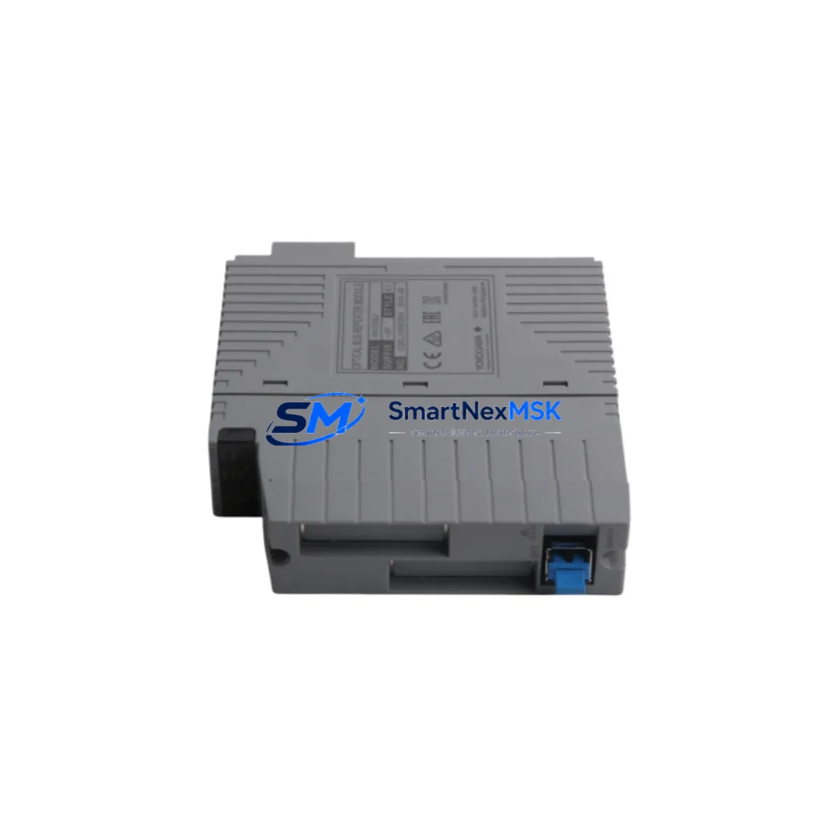
YOKOGAWA ANT502-5F S1 Maintenance-Ready Spare for CENTUM VP Automation
The YOKOGAWA ANT502-5F S1 is an original relay contact output module designed for the CENTUM VP Distributed Control System (DCS) platform — one of the most widely deployed process automation architectures in refining, petrochemical, power generation, and pharmaceutical manufacturing. As a maintenance-ready spare, the ANT502-5F S1 is a critical component for any facility operating CENTUM VP field control stations (FCS), where relay output channels drive solenoid valves, motor starters, alarm annunciators, and interlock circuits.
Unplanned downtime caused by a failed relay output module can cascade across an entire control loop. Facilities that maintain a verified, tested ANT502-5F S1 on the shelf eliminate the lead-time risk associated with sourcing obsolete or long-cycle DCS components. This module ships fully tested, with function verification completed prior to dispatch, and is backed by a 12-month warranty covering manufacturing defects and operational failure under normal service conditions.
Whether you are executing a planned turnaround, responding to a fault alarm, or building out your critical spare inventory, the ANT502-5F S1 is a direct, compatible replacement for the installed base across CENTUM VP R5, R6, and legacy CENTUM CS 3000 field control stations where cross-compatibility has been confirmed by engineering review.
Spare Maintenance Table
| Parameter | Specification / Detail |
|---|---|
| Part Number / SKU | ANT502-5F S1 |
| Manufacturer | YOKOGAWA Electric Corporation |
| Module Type | Relay Contact Output Module |
| Compatible Platform | CENTUM VP DCS (FCS, LFCS, PFCS); CENTUM CS 3000 (compatibility subject to engineering review) |
| Output Type | Dry relay contact output |
| Number of Output Channels | 16 channels (typical for ANT5xx series) |
| Contact Rating | 250 VAC / 30 VDC, 2A resistive (per channel) |
| Isolation | Channel-to-channel and channel-to-bus optical isolation |
| Power Supply | Supplied via CENTUM VP I/O bus backplane |
| Installation | Hot-swap capable on supported FCS node configurations |
| Operating Temperature | 0°C to 55°C (32°F to 131°F) |
| Humidity | 10% to 90% RH, non-condensing |
| Country of Origin | Japan |
| Weight | Approx. 1,240 g (module with housing) |
| Maintenance Recommendation | Inspect relay contact wear every 12–18 months; replace proactively in high-cycle interlock applications |
| Warranty | 12 months from date of shipment — covers manufacturing defects and operational failure under normal service conditions |
| Pre-shipment Testing | Function-verified and continuity-tested prior to dispatch |
Maintenance Planning for Continuous Operation
When a relay output module such as the ANT502-5F S1 is flagged for replacement during a control cabinet inspection or fault diagnosis, experienced maintenance engineers treat the event as a trigger for a broader system health review. A single failed relay channel rarely occurs in isolation — it is often a symptom of aging components, thermal stress, or accumulated contact wear across the I/O node.
During the same maintenance window, engineers should inspect the ANT501 digital input module installed in the same FCS node, as input/output modules in the same rack share backplane power and bus communication. If the ANT502-5F S1 has been in service for more than five years, the ANT11D or ANT13D analog input modules in adjacent slots should be checked for drift and calibration status.
The ACM11 or ACM12 communication module responsible for Vnet/IP or ESB-Bus communication between the FCS and the HIS (Human Interface Station) should be verified for error-free operation, as relay output faults can sometimes be misdiagnosed when the root cause is a communication timeout rather than a hardware failure. Similarly, the CP451 or CP461 field control processor should be checked for CPU load, memory status, and firmware revision compatibility with the replacement module.
Power supply redundancy is a critical checkpoint: the PW481 or PW482 dual-redundant power supply modules feeding the I/O node should be load-tested and inspected for capacitor aging. A degraded power supply can cause intermittent relay output faults that are difficult to reproduce under bench conditions. The terminal assembly (TA) or marshalling terminal block connected to the ANT502-5F S1 field wiring should be inspected for loose terminations, corrosion, and insulation resistance.
For facilities running CENTUM VP in SIL-rated safety loops, the replacement of any relay output module should be coordinated with a review of the associated safety relay module or SIS interface card, and the field wiring continuity to the final element (valve or actuator) should be confirmed before returning the loop to automatic control. Where signal conditioning is used between the DCS output and the field device, signal isolators or loop-powered barriers in the marshalling cabinet should be inspected for proper operation.
Maintaining a structured spare parts kit that includes the ANT502-5F S1 alongside the ANT501 digital input module, ACM11 communication module, and PW481 power supply ensures that the most common single-point failure modes in a CENTUM VP FCS node can be resolved within a single maintenance shift, minimizing mean time to repair (MTTR) and protecting production continuity.
Site Replacement Workflow
Step 1 — Pre-replacement verification: Confirm the fault is isolated to the ANT502-5F S1 by reviewing the FCS diagnostic screen on the HIS. Check for channel-specific fault codes (e.g., relay coil open, contact weld, or output discrepancy alarm). Export the current I/O assignment and tag list for the affected module before proceeding.
Step 2 — Safe isolation: Place all output channels in manual or safe-state via the CENTUM VP engineering console. For interlock-critical outputs, coordinate with the process safety team before de-energizing. Confirm field devices (valves, motors) are in a safe position.
Step 3 — Hot-swap or cold-swap removal: On FCS nodes that support hot-swap, the ANT502-5F S1 can be removed and replaced without powering down the node. Verify hot-swap capability in the FCS hardware manual for your specific node type. For cold-swap, follow the CENTUM VP shutdown and restart procedure for the affected FCS.
Step 4 — Module installation and recognition: Insert the replacement ANT502-5F S1 into the correct slot. The FCS will automatically recognize the module and restore the I/O configuration from the control database. Verify module status on the HIS diagnostic screen — all channels should show normal status within 30 seconds of insertion.
Step 5 — Loop check and return to service: Perform a channel-by-channel output test from the HIS engineering console. Confirm field device response for each active channel. Return outputs to automatic control sequentially, monitoring for alarm conditions. Update the maintenance log with the replacement date, module serial number, and test results.
This workflow is compatible with CENTUM VP R5.04 and later. For earlier revisions, consult the YOKOGAWA hardware replacement guide (IM 33J01B30-01EN) for version-specific procedures.
Spare Parts Support FAQ
Q1: Is the ANT502-5F S1 compatible with both CENTUM VP and CENTUM CS 3000?
The ANT502-5F S1 is designed and catalogued for CENTUM VP. Compatibility with CENTUM CS 3000 depends on the specific FCS hardware revision and software version. Engineering confirmation is recommended before installation in a CS 3000 system. Contact our technical team with your FCS model and software revision for a compatibility assessment prior to ordering.
Q2: What pre-shipment testing is performed on the ANT502-5F S1?
Every unit undergoes function verification including relay coil energization testing, contact continuity measurement across all channels, and bus interface communication check. Test records are available upon request. Units that do not pass all test criteria are not dispatched.
Q3: How should the ANT502-5F S1 be stored as a long-term spare?
Store in original anti-static packaging in a climate-controlled environment (10°C–30°C, 20%–70% RH, non-condensing). Avoid storage near strong magnetic fields or corrosive atmospheres. For long-term storage exceeding 24 months, perform a relay contact exercise test (energize/de-energize each channel 10 cycles) before installation to prevent contact oxidation.
Q4: What does the 12-month warranty cover, and how is a warranty claim processed?
The 12-month warranty covers manufacturing defects and operational failure under normal service conditions from the date of shipment. It does not cover damage caused by incorrect installation, overvoltage, or physical impact. To initiate a warranty claim, contact sales@smartnexmsk.com with the order reference, installation date, and a description of the failure mode. Replacement or repair will be arranged within 5 business days of claim confirmation.
© 2026 SMARTNEXMSK. All rights reserved.
Original Source: https://smartnexmsk.com
Contact: sales@smartnexmsk.com | +86 18259474341


