Yokogawa DTSX200-N0EN Maintenance-Ready Spare for DTSX Automation
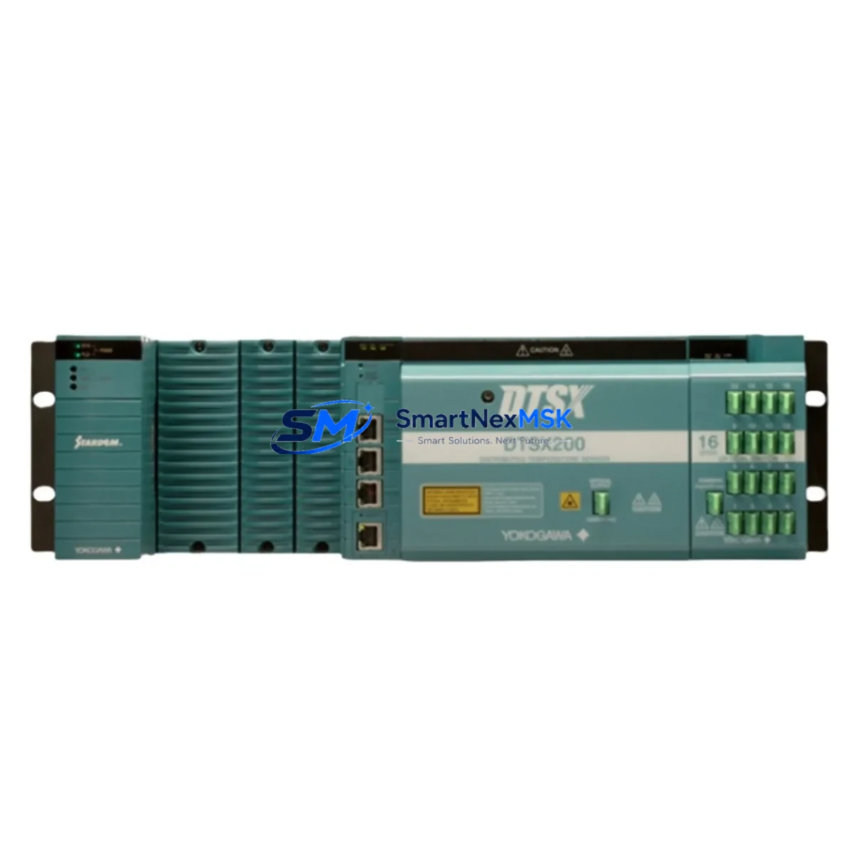
The Yokogawa DTSX200-N0EN is a fiber optic Distributed Temperature Sensing (DTS) unit engineered for continuous industrial monitoring in process automation, pipeline surveillance, power cable management, and hazardous-area temperature profiling. As a maintenance-ready original spare, the DTSX200-N0EN enables maintenance engineers and procurement teams to minimize unplanned downtime by holding a verified replacement unit on-site or in the regional spare parts warehouse. When a DTSX system goes offline, every hour of diagnostic delay translates directly into production loss or safety risk — having a pre-tested DTSX200-N0EN on the shelf is the single most effective insurance against extended outages.
The DTSX200-N0EN operates within the Yokogawa DTSX Series platform, which is widely deployed in oil & gas pipelines, LNG terminals, power generation facilities, tunnel fire detection systems, and large-scale industrial plants. Its fiber optic sensing architecture eliminates electromagnetic interference concerns common in high-voltage environments, making it a preferred choice for control engineers managing complex electrical infrastructure. Replacement of this unit requires no re-engineering of the sensing fiber layout, provided the same DTSX Series topology is maintained — a key advantage for rapid site restoration.
From a procurement perspective, the DTSX200-N0EN is a long-lifecycle component with a well-established supply chain. Sourcing an original spare from a verified distributor — rather than waiting for OEM lead times during an emergency — is standard practice in facilities with mature maintenance programs. Our stock is tested prior to shipment, accompanied by inspection documentation, and covered by a 12-month warranty against manufacturing defects.
Spare Maintenance Table
| Parameter | Specification / Detail |
|---|---|
| SKU / Part Number | DTSX200-N0EN |
| Brand | Yokogawa Electric Corporation |
| Series | DTSX Series (Distributed Temperature Sensing) |
| Product Type | Fiber Optic DTS Unit |
| Sensing Technology | Raman Backscattering / Fiber Optic |
| Typical Sensing Range | Up to 30 km (model-dependent, DTSX200 class) |
| Temperature Accuracy | ±1°C (typical, application-dependent) |
| Communication Interface | Ethernet (Modbus TCP / HART compatible configurations) |
| Power Supply | 100–240 VAC, 50/60 Hz (verify with site specification) |
| Operating Temperature | 0°C to +50°C (control room / enclosure installation) |
| Country of Origin | Japan |
| Compatibility | Yokogawa DTSX Series; integrates with CENTUM VP, ProSafe-RS, and third-party DCS via standard protocols |
| Installation | 19-inch rack mount or panel mount; fiber connector per site design |
| Maintenance Recommendation | Annual fiber continuity check; optical power level verification; firmware version audit |
| Warranty | 12 Months — tested and verified before shipment |
Maintenance Planning for Continuous Operation
When scheduling a planned replacement or responding to a DTSX200-N0EN fault alarm, maintenance engineers should treat the event as an opportunity to audit the broader temperature monitoring loop and associated control infrastructure. A fiber optic DTS unit does not operate in isolation — its reliability depends on the integrity of every upstream and downstream component in the measurement chain.
Begin with the fiber optic sensing cable itself: inspect connectors, splice points, and bend radii for degradation, especially in installations exposed to mechanical vibration or thermal cycling. Next, verify the optical patch panel and any fiber distribution frames in the cabinet — contaminated or misaligned connectors are a leading cause of signal loss that is often misdiagnosed as a DTS unit failure.
On the power side, confirm that the 24 VDC or 100–240 VAC power supply module feeding the DTSX200-N0EN is within specification. A marginal power supply can cause intermittent resets that mimic sensor faults. If the unit shares a distribution rail with other instruments, check the DIN rail terminal blocks and circuit breakers for loose connections or thermal discoloration.
For sites where the DTSX200-N0EN feeds data into a Yokogawa CENTUM VP DCS or a ProSafe-RS safety system, verify the communication gateway or serial/Ethernet converter module is functioning correctly. A failed communication card can isolate the DTS data from the control layer even when the sensing unit itself is healthy. Similarly, if the system uses a Modbus RTU-to-TCP converter or a signal isolator between the DTS output and the DCS input card, these should be tested during the same maintenance window.
In control cabinets housing the DTSX200-N0EN alongside I/O modules, relay output cards, and analog input cards, perform a full cabinet inspection: check for dust accumulation on ventilation slots, verify that cabinet cooling fans are operational, and confirm that surge protection devices on signal lines are not in a tripped or degraded state. For older installations, inspect the backplane or rack chassis for corrosion on connector pins, which can cause intermittent communication errors.
If the site uses a local HMI panel or operator workstation to display DTSX temperature profiles, confirm that the display software and driver versions are compatible with the replacement unit’s firmware. A firmware mismatch between the DTSX200-N0EN and the HMI configuration can result in incorrect alarm thresholds or missing trend data after replacement.
Site Replacement Workflow
Step 1 — Pre-replacement verification: Confirm the replacement DTSX200-N0EN matches the installed unit’s firmware version and hardware revision. Review the site’s as-built documentation for fiber connector type (SC/APC, FC/APC, or LC) and cable routing. Obtain the current DTS configuration file (zone definitions, alarm setpoints, measurement intervals) from the DCS historian or local backup.
Step 2 — Safe isolation: Isolate the DTSX200-N0EN from the control system using the appropriate inhibit or bypass function in the DCS. Do not simply power down without notifying the control room, as loss of temperature monitoring may trigger safety interlocks in some process configurations.
Step 3 — Physical replacement: Disconnect fiber connectors carefully — clean both the unit-side and cable-side connectors with an appropriate fiber optic cleaning tool before reconnecting to the new unit. Reconnect power and communication cables per the original wiring diagram. Avoid over-tightening fiber connectors.
Step 4 — Commissioning: Power up the replacement DTSX200-N0EN and allow it to complete its self-test sequence. Restore the saved configuration file. Verify that temperature readings across all defined zones match expected ambient values before releasing the bypass. Document the replacement in the site maintenance log with the new unit’s serial number and firmware version.
Step 5 — Post-replacement monitoring: Monitor the system for 24–48 hours after replacement to confirm stable operation. Check for any alarm events or communication errors in the DCS event log. Archive the replaced unit’s fault log if accessible for root cause analysis.
This workflow applies equally to planned lifecycle replacements of aging DTSX200-N0EN units and to emergency swap-outs following unexpected failures. Maintaining a tested spare on-site reduces the replacement cycle from days (OEM order lead time) to hours.
Spare Parts Support FAQ
Q1: Is the DTSX200-N0EN a direct drop-in replacement for older DTSX Series units?
The DTSX200-N0EN is designed for compatibility within the Yokogawa DTSX Series platform. In most installations, it is a direct functional replacement for units of the same model designation. However, firmware versions and hardware revisions should be verified against the site’s DCS configuration before installation. Our technical team can assist with compatibility confirmation prior to shipment.
Q2: How is the unit tested before shipment?
Each DTSX200-N0EN unit undergoes a pre-shipment functional test covering power-on self-test, optical output verification, and communication interface check. Units that do not pass all test criteria are not dispatched. A test record is available upon request. The 12-month warranty covers manufacturing defects identified after installation under normal operating conditions.
Q3: What is the recommended spare parts inventory strategy for DTSX systems?
For facilities with a single DTSX200-N0EN installation, holding one on-site spare is the minimum recommended posture. For multi-unit installations or critical safety monitoring applications (e.g., tunnel fire detection, LNG leak detection), a 1:4 or 1:6 spare ratio is common practice. Spare units should be stored in a clean, dry environment within the manufacturer’s specified storage temperature range and inspected annually.
Q4: Can you supply other DTSX Series components or related Yokogawa spare parts?
Yes. In addition to the DTSX200-N0EN, we maintain stock of related Yokogawa components including CENTUM VP I/O modules, ProSafe-RS safety controller cards, power supply modules, and communication interface units. Contact our sales team with your full BOM or spare parts list for availability and lead time confirmation.
© 2026 SMARTNEXMSK. All rights reserved.
Original Source: https://smartnexmsk.com
Contact: sales@smartnexmsk.com | +86 18259474341


