Yokogawa EB501-10 S2 Spare for CENTUM VP Automation: Spare Replacement & Industrial Downtime Risk Control
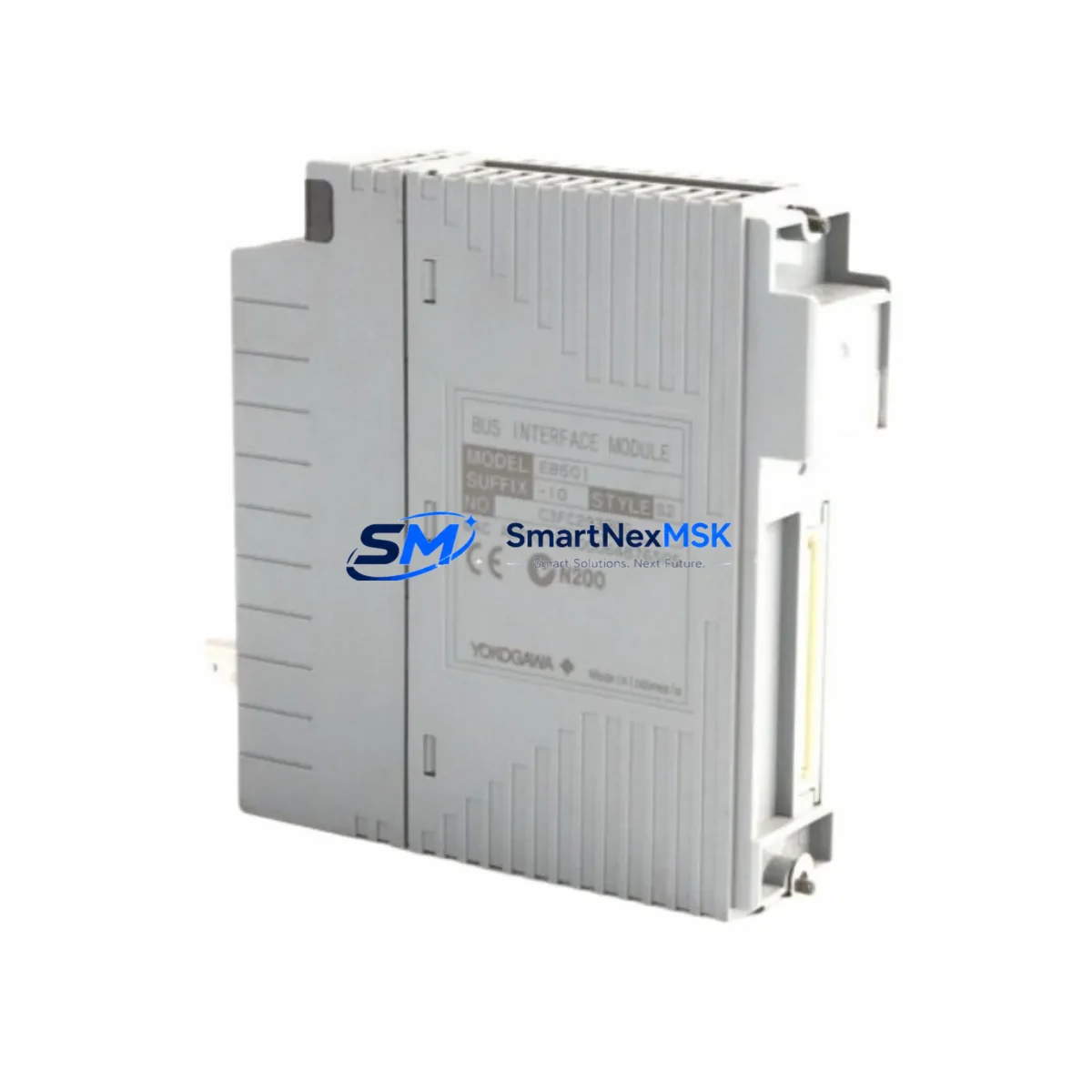
The Yokogawa EB501-10 S2 is an original ESB (Enhanced Signal Bus) Bus Interface Module designed for deployment within CENTUM VP and CS 3000 Distributed Control Systems. As a critical communication bridge between field control stations (FCS) and I/O subsystems, this module plays a central role in maintaining real-time data exchange across the ESB backbone. For maintenance engineers managing aging DCS infrastructure, securing a verified original spare of the EB501-10 S2 is a foundational step in any proactive downtime prevention strategy.
At SMARTNEXMSK, every EB501-10 S2 unit is sourced as an original Yokogawa component, individually tested prior to dispatch, and backed by a 12-month warranty. We maintain long-term inventory to support both emergency replacement and planned maintenance cycles, ensuring your procurement team can act quickly when a fault is detected or a scheduled overhaul is due.
Spare Maintenance Table
| Parameter | Specification / Detail |
|---|---|
| Part Number / SKU | EB501-10 S2 |
| Manufacturer | Yokogawa Electric Corporation |
| Module Type | ESB Bus Interface Module |
| Compatible Systems | CENTUM VP, CENTUM CS 3000 |
| Bus Interface | ESB (Enhanced Signal Bus) |
| Installation | Rack-mount, FCS / RIO cabinet |
| Power Supply Compatibility | Supplied via backplane from FCS power module (e.g., PW481, PW482 series) |
| Operating Temperature | 0°C to 55°C (standard industrial environment) |
| Origin | Japan |
| Product Condition | Original, new or tested-good surplus |
| Pre-shipment Testing | Function-verified before dispatch |
| Warranty | 12 Months |
| Lead Time | In-stock; ships within 2–5 business days |
| Maintenance Recommendation | Inspect ESB cabling, backplane connectors, and adjacent I/O modules during replacement |
Maintenance Planning for Continuous Operation
When a CENTUM VP or CS 3000 system flags an ESB communication fault or the EB501-10 S2 module is identified as the failure point during fault isolation, the replacement process should be treated as an opportunity for a broader cabinet inspection. Maintenance engineers should not limit their scope to the failed module alone — the surrounding system components are equally subject to wear, thermal stress, and connector degradation.
Begin by verifying the integrity of the ESB bus cable assemblies connecting the FCS to remote I/O units. Damaged or loose ESB connectors are a common secondary cause of recurring bus faults even after a module swap. Next, inspect the backplane itself for signs of oxidation or mechanical damage at the module slot. The power supply modules — typically from the PW481 or PW482 series — should be checked for output voltage stability, as undervoltage conditions can cause intermittent bus interface failures that mimic module faults.
On the I/O side, review the status of analog input modules (e.g., AAI141, AAI143) and analog output modules (e.g., AAO141) connected downstream of the ESB interface. A bus interface failure can mask underlying I/O channel faults that only become apparent after the bus is restored. Digital I/O modules such as ADV151 or ADV161 should also be scanned for channel-level alarms. If the system includes relay output modules (e.g., ADV557), verify contact integrity and coil response after the bus is re-established.
For systems with communication modules handling HART pass-through or fieldbus integration, confirm that the communication module (e.g., ALF111 for FOUNDATION Fieldbus) resumes normal polling after the EB501-10 S2 is replaced. In cabinets where signal isolators or barriers are installed between field instruments and I/O cards, inspect these components for signs of drift or failure — they are often overlooked during bus-level fault investigations.
If the control cabinet includes an HMI engineering station or operator station connected via Vnet/IP, verify that the FCS node re-registers correctly on the network after the module replacement. Terminal blocks and wiring ferrules in the I/O marshalling section should also be inspected for loose connections, particularly in high-vibration environments. Maintaining a cabinet-level spare kit that includes the EB501-10 S2 alongside power modules, ESB cables, and representative I/O modules significantly reduces mean time to repair (MTTR) during unplanned outages.
Site Replacement Workflow
The EB501-10 S2 is designed for hot-swap or cold-swap replacement depending on the FCS configuration and site safety procedures. Before initiating replacement, confirm the module slot address and ESB node assignment in the CENTUM VP System Builder or CS 3000 System View to ensure the replacement unit is configured identically to the failed module. Mismatched node addresses are a common cause of post-replacement communication failures.
Power down the affected FCS or RIO cabinet according to your site lockout/tagout (LOTO) procedure. Remove the failed EB501-10 S2 by releasing the module locking lever and sliding it out of the backplane slot. Inspect the backplane connector pins for damage before inserting the replacement unit. Seat the new module firmly until the locking lever engages, then restore power and monitor the system status display for ESB link confirmation.
For sites migrating from CS 3000 to CENTUM VP, the EB501-10 S2 maintains backward compatibility within the ESB architecture, making it a viable replacement for older bus interface modules without requiring firmware reconfiguration in most cases. This compatibility reduces migration risk and allows maintenance teams to standardize their spare parts inventory across both system generations, extending the operational life of legacy installations while a full system upgrade is planned.
After replacement, perform a full I/O scan from the HMI to confirm all downstream field signals are reading correctly. Document the replacement in your CMMS with the module serial number, slot location, and post-replacement test results to support future maintenance audits and warranty claims.
Spare Parts Support FAQ
Q1: Is the EB501-10 S2 compatible with both CENTUM VP and CS 3000 systems?
Yes. The EB501-10 S2 is designed for use within the ESB bus architecture shared by CENTUM VP and CS 3000 platforms. It can replace failed bus interface modules in either system generation without requiring changes to the ESB node configuration in most standard installations. Always verify the slot address and firmware revision in System Builder before installation.
Q2: How is each unit tested before shipment?
Every EB501-10 S2 supplied by SMARTNEXMSK undergoes functional verification prior to dispatch. Testing confirms bus interface communication, backplane connector integrity, and module self-diagnostics. A test report is available upon request. All units are shipped with ESD-protective packaging to prevent damage in transit.
Q3: What does the 12-month warranty cover?
The 12-month warranty covers manufacturing defects and functional failures under normal operating conditions. It does not cover damage resulting from incorrect installation, overvoltage events, or physical mishandling. In the event of a warranty claim, SMARTNEXMSK will arrange replacement or repair with priority lead time to minimize your system downtime.
Q4: Can SMARTNEXMSK support long-term or recurring procurement of the EB501-10 S2?
Yes. We maintain standing inventory of the EB501-10 S2 and can support blanket purchase orders, annual maintenance contracts, and emergency spot procurement. For sites with multiple CENTUM VP or CS 3000 cabinets, we recommend establishing a minimum stock level of one to two units per ESB segment as part of your critical spare parts strategy.
© 2026 SMARTNEXMSK. All rights reserved.
Original Source: https://smartnexmsk.com
Contact: sales@smartnexmsk.com | +86 18259474341


