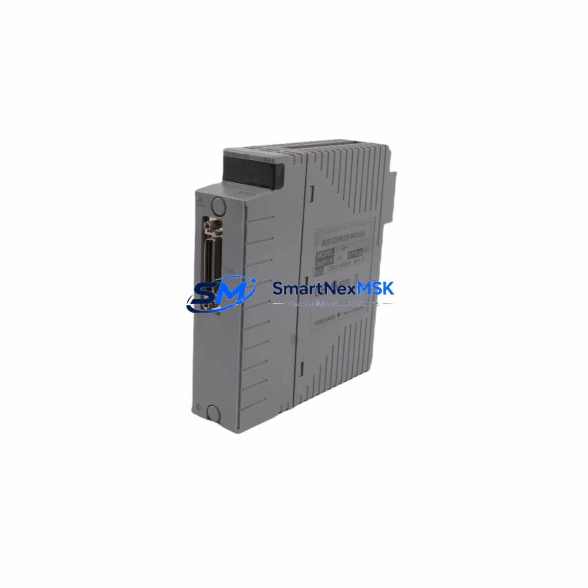
Yokogawa EC401-50 S3 Spare for CENTUM VP Automation
The Yokogawa EC401-50 S3 is an original bus coupler module designed for the CENTUM VP distributed control system — one of the most widely deployed DCS platforms in refining, petrochemical, power generation, and continuous process industries. As a maintenance-ready spare part, the EC401-50 S3 plays a critical role in sustaining field bus communication integrity between I/O units and the control network. When this module fails or degrades, the consequences can range from intermittent signal loss to complete I/O segment dropout, triggering unplanned shutdowns and costly production interruptions.
Sourced as an original Yokogawa component, this spare is tested prior to shipment and backed by a 12-month warranty. It is stocked to support rapid deployment in emergency replacement scenarios, planned maintenance windows, and long-term spare parts inventory programs for aging CENTUM VP installations.
Spare Maintenance Table
| Parameter | Specification |
|---|---|
| Part Number | EC401-50 S3 |
| Brand | Yokogawa Electric Corporation |
| Module Type | Bus Coupler Module |
| Compatible System | CENTUM VP DCS |
| Series | CENTUM VP / CENTUM CS 3000 (compatible) |
| Communication Bus | Vnet/IP Field Bus |
| Origin | Japan |
| Installation | DIN rail / backplane slot mount |
| Operating Temperature | 0°C to 60°C |
| Power Supply | Via system backplane (24 VDC nominal) |
| Application Environment | Industrial control cabinet, DCS I/O room |
| Maintenance Recommendation | Inspect annually; replace on communication fault or CRC error escalation |
| Condition | Original, new or refurbished-tested |
| Warranty | 12 Months |
| Pre-shipment Test | Function verified before dispatch |
Maintenance Planning for Continuous Operation
Replacing the EC401-50 S3 bus coupler is rarely an isolated task. Experienced maintenance engineers know that a bus coupler fault is often symptomatic of broader stress in the I/O segment. During any planned replacement, the following components in the same control cabinet or electrical loop should be inspected concurrently to prevent repeat failures and maximize uptime:
The Yokogawa AMN11 or AMN21 node unit that hosts the EC401-50 S3 should be checked for backplane connector wear and firmware version compatibility. Adjacent AAI141 or AAI143 analog input modules sharing the same I/O bus segment may exhibit signal drift if the coupler has been operating in a degraded state — verify channel calibration after replacement. The ADV151 or ADV161 digital input/output modules in the same nest should be inspected for contact wear and proper termination.
On the power side, the Yokogawa PW481 or PW482 power supply module feeding the I/O nest should be load-tested; a marginal power supply is a common root cause of intermittent bus coupler faults. Check the 24 VDC distribution terminal blocks and fuse holders in the cabinet for loose connections or blown fuses that may have contributed to the original fault condition.
For communication integrity, inspect the Vnet/IP communication cables and RJ45 connectors between the bus coupler and the field control station (FCS). Damaged shielding or improper grounding on these cables can cause recurring CRC errors that mimic module failure. If the installation includes a Yokogawa ESB bus repeater, verify its status and signal levels as well.
Where the CENTUM VP system interfaces with field instruments, review the HART multiplexer or signal isolator modules connected downstream of the I/O cards. A failed bus coupler can mask underlying instrument faults that only become visible after the coupler is restored. Finally, if the control cabinet includes an HMI engineering station or operator console connected via the same Vnet/IP segment, confirm that communication is fully restored and that no alarm suppression was left active during the maintenance window.
Site Replacement Workflow
Replacing the EC401-50 S3 in a live CENTUM VP system requires careful sequencing to minimize disruption. Begin by identifying the affected I/O node in the CENTUM VP system builder and confirming the module address and slot position. If the system supports hot-standby or redundant bus coupler configuration, initiate a controlled switchover to the standby path before removing the faulty module — this eliminates the need for a full process shutdown in many installations.
For non-redundant configurations, coordinate with the process control team to place the affected I/O segment in manual mode and notify field operators before proceeding. Remove the EC401-50 S3 by releasing the module latch and sliding it clear of the backplane. Inspect the backplane connector pins for corrosion or mechanical damage before inserting the replacement unit. After seating the new module, allow the CENTUM VP FCS to perform automatic I/O re-initialization — this typically completes within 30 to 90 seconds depending on the node configuration.
Verify all I/O channels on the restored segment are reading correctly in the operator station before returning the loop to automatic control. Document the replacement in the maintenance management system (CMMS) with the module serial number, installation date, and any observations about the failed unit. This record supports future spare parts planning and warranty claims.
For sites migrating from older CENTUM CS 3000 hardware, the EC401-50 S3 is compatible with select CS 3000 node configurations — confirm the hardware revision and firmware baseline with your Yokogawa service representative before installation to ensure seamless backward compatibility and avoid configuration mismatches.
Spare Parts Support FAQ
Q1: What is the shelf life and storage requirement for the EC401-50 S3 spare?
The EC401-50 S3 should be stored in its original anti-static packaging in a dry, temperature-controlled environment (10°C to 40°C, relative humidity below 75% non-condensing). Under these conditions, the module can be stored for up to 5 years without performance degradation. Inspect the module annually if held in long-term stock and verify firmware compatibility before deployment.
Q2: How is compatibility with my existing CENTUM VP version confirmed before shipment?
Our technical team cross-references the EC401-50 S3 hardware revision against the CENTUM VP system version and FCS firmware baseline provided by the customer. Where compatibility requires verification, we can arrange pre-shipment configuration checks. Customers are encouraged to provide their system builder project version and node hardware list to expedite this process.
Q3: What does the 12-month warranty cover for this spare part?
The 12-month warranty covers manufacturing defects and functional failures under normal operating conditions as specified in the Yokogawa CENTUM VP hardware manual. It does not cover damage resulting from incorrect installation, overvoltage events, or use outside the rated environmental specifications. Warranty claims are supported with a return merchandise authorization (RMA) process and replacement dispatch within 5 business days upon fault confirmation.
Q4: Can this module be used as a direct drop-in replacement for an older EC401-50 revision?
In most cases, yes — the EC401-50 S3 is designed as a form-fit-function replacement for earlier EC401-50 revisions within the CENTUM VP platform. However, sites running legacy firmware or non-standard node configurations should verify the hardware revision compatibility matrix before installation. Our team provides pre-sales technical support to confirm suitability for your specific system configuration at no additional cost.
© 2026 SMARTNEXMSK. All rights reserved.
Original Source: https://smartnexmsk.com
Contact: sales@smartnexmsk.com | +86 18259474341


