
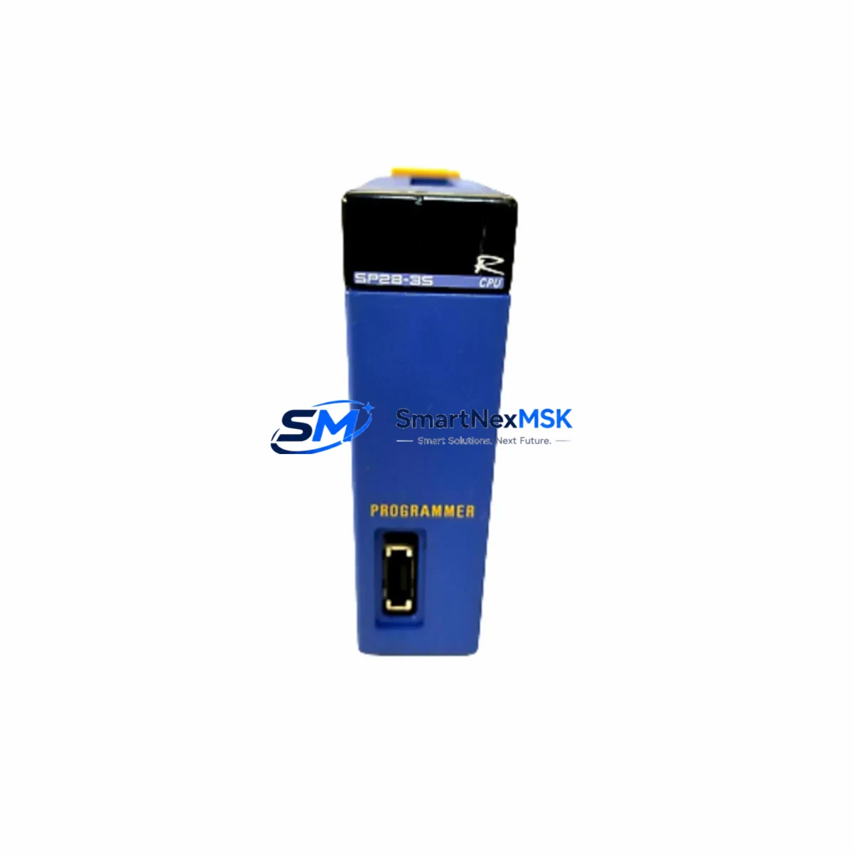
Yokogawa F3SP28-3S Maintenance-Ready Spare for FA-M3 Automation
The Yokogawa F3SP28-3S is a Sequence CPU Module designed for the FA-M3 Range-free Multi-controller platform — one of the most widely deployed process and factory automation controllers in continuous manufacturing, utilities, and heavy industry. When this CPU module fails or degrades, the entire FA-M3 rack loses its execution engine, triggering a full control-system shutdown. Holding a verified, tested spare on-site is the single most effective strategy to compress mean time to repair (MTTR) and protect production continuity.
This listing supplies an original Yokogawa F3SP28-3S sourced through authorized industrial channels. Every unit undergoes pre-shipment functional verification covering power-on self-test, I/O bus communication, and program memory integrity before dispatch. A 12-month warranty is included as standard, covering manufacturing defects and functional failures under normal operating conditions.
Spare Maintenance Table
| Parameter | Specification / Value |
|---|---|
| Model / SKU | F3SP28-3S |
| Brand | YOKOGAWA |
| Series / Platform | FA-M3 Range-free Multi-controller |
| Module Type | Sequence CPU Module |
| Program Memory | 28K steps (ladder / function block) |
| Scan Time | Approx. 0.1 ms / 1K steps (basic instruction) |
| I/O Points Supported | Up to 2,048 I/O points (system-dependent) |
| Communication Ports | RS-232C loader port; optional Ethernet via F3LE01/F3LE11 modules |
| Backplane Compatibility | FA-M3 standard base units (F3BU04, F3BU08, F3BU13) |
| Power Supply Requirement | Supplied via FA-M3 power module (F3PU20, F3PU40 series) |
| Operating Temperature | 0 °C to 55 °C |
| Relative Humidity | 10% to 90% RH (non-condensing) |
| Vibration Resistance | IEC 60068-2-6 compliant |
| Country of Origin | Japan |
| Condition | Original / Genuine — pre-shipment tested |
| Warranty | 12 Months — functional defect coverage |
| Typical Lead Time | Ships within 3–7 business days |
| Application Environment | Process automation, utilities, discrete manufacturing, water treatment |
Maintenance Planning for Continuous Operation
A CPU module replacement rarely occurs in isolation. When a maintenance or reliability engineer identifies a failed or suspect F3SP28-3S, the surrounding FA-M3 cabinet should be systematically inspected before the new module is commissioned. Skipping adjacent component checks is a leading cause of repeat failures and extended downtime.
Power supply integrity is the first checkpoint. The F3PU20 or F3PU40 power supply module feeds the entire FA-M3 backplane; a degraded capacitor bank or output voltage drift can stress a replacement CPU within hours of installation. Measure DC rail voltages under load before inserting the new F3SP28-3S.
I/O module condition is the second priority. Digital input modules such as the F3XD32 and digital output modules such as the F3YD32 share the I/O bus with the CPU. A shorted output channel or a field wiring fault that caused the original CPU failure may still be present. Isolate and test each I/O module before restoring the rack to service.
Communication and network modules must also be verified. If the FA-M3 system uses an F3LE11 Ethernet module for SCADA connectivity or an F3LP02 PROFIBUS-DP module for field device integration, confirm that these modules respond correctly on the network after CPU swap. A communication module that was marginal before the failure may not re-establish its link with a new CPU without a cold restart or firmware re-sync.
Relay output modules and terminal blocks in the same cabinet deserve attention during any planned CPU replacement. Relay contacts in modules like the F3YR16 accumulate switching cycles and may be near end-of-life. Inspect contact resistance and replace any relay module showing signs of arc erosion or intermittent continuity. Similarly, check F3TB-series terminal blocks for loose screws, oxidized connections, or insulation degradation — these are common sources of spurious I/O signals that can trigger CPU faults.
Signal isolation and protection components should be part of every FA-M3 maintenance checklist. Analog signal isolators installed between field transmitters and the F3AD04 or F3AD08 analog input modules protect the CPU from ground loops and transient overvoltage. If the original CPU failure was preceded by unexplained analog channel errors, inspect or replace the signal isolators before returning the system to automatic control.
Finally, review the fuse and surge protection devices on the incoming power feed to the control cabinet. A blown fuse or a degraded MOV on the 24 VDC supply rail is easy to overlook but can cause the same failure mode to recur. Replacing the F3SP28-3S without restoring proper upstream protection is an incomplete repair.
Site Replacement Workflow
Step 1 — Pre-replacement documentation: Before powering down, use Yokogawa’s WideField3 programming software to upload and save the current ladder program, I/O assignments, and system parameters from the existing F3SP28-3S (if the module is still partially functional). Store the backup on a local engineering workstation and a network share. If the module is completely unresponsive, retrieve the last known-good program backup from your version control archive.
Step 2 — Safe power-down: Follow the FA-M3 shutdown sequence — place the CPU in STOP mode, confirm all outputs are de-energized, then remove power from the F3PU20/F3PU40 power module. Wait for the backplane capacitors to discharge (minimum 30 seconds) before handling any modules.
Step 3 — Module swap: Remove the failed F3SP28-3S by releasing the top and bottom locking levers. Insert the replacement module firmly until the bus connector seats fully. Re-engage the locking levers. Do not apply force — if resistance is felt, check for bent connector pins on the backplane.
Step 4 — Program restore and parameter configuration: Power up the rack and connect WideField3 via the RS-232C loader port or Ethernet (if an F3LE11 is installed). Download the saved program and verify I/O module configuration matches the physical rack layout. Set the CPU operating mode, scan watchdog timer, and communication parameters to match the previous configuration.
Step 5 — Functional verification: Run the system in MONITOR mode with outputs inhibited. Confirm all I/O channels read correctly, communication modules report healthy status, and no diagnostic error codes are active. Only then transfer to RUN mode and restore normal operation. Document the replacement date, module serial number, and test results in the equipment maintenance log.
This structured workflow minimizes the risk of introducing secondary faults during the replacement and ensures the FA-M3 system returns to service in a fully verified state — typically within 2–4 hours for a prepared maintenance team holding a tested spare.
Spare Parts Support FAQ
Q1: Is this F3SP28-3S a genuine Yokogawa original or a compatible substitute?
This is an original Yokogawa F3SP28-3S module sourced through established industrial supply channels. It is not a clone, compatible substitute, or refurbished unit sold as new. Each unit is individually verified before shipment. If you require a certificate of conformance or traceability documentation, please contact our sales team prior to ordering.
Q2: How many F3SP28-3S units should I hold in my spare parts inventory?
For facilities running FA-M3 systems in critical process control roles — such as utilities, chemical processing, or continuous manufacturing — we recommend a minimum of one cold spare per site, with a second unit held at a regional warehouse if multiple FA-M3 racks are deployed. CPU modules have no scheduled replacement interval under normal operating conditions, but age-related EEPROM wear and capacitor degradation become relevant after 10–15 years of continuous service. Proactive spare stocking before the module reaches end-of-production status is strongly advised.
Q3: What compatibility checks should I perform before installing the replacement module?
Confirm that the FA-M3 base unit (F3BU04, F3BU08, or F3BU13) and the installed power module (F3PU20 or F3PU40) are in good condition and within specification. Verify that the WideField3 software version used for programming is compatible with the F3SP28-3S firmware revision. If the system includes optional modules such as the F3LE11 Ethernet module or F3LP02 PROFIBUS-DP module, confirm their firmware versions are compatible with the replacement CPU. No hardware modification is required for a like-for-like F3SP28-3S swap within the same FA-M3 rack generation.
Q4: What does the 12-month warranty cover, and what is the claims process?
The 12-month warranty covers functional failures and manufacturing defects under normal operating conditions — correct supply voltage, operating temperature within 0–55 °C, and installation per Yokogawa FA-M3 system documentation. It does not cover damage caused by incorrect wiring, overvoltage events, physical impact, or unauthorized modification. To initiate a warranty claim, contact [email protected] with the order reference, module serial number, and a description of the failure symptom. Replacement or repair will be arranged within 5 business days of claim confirmation.
© 2026 SMARTNEXMSK. All rights reserved.
Original Source: https://smartnexmsk.com
Contact: [email protected] | +86 18259474341



