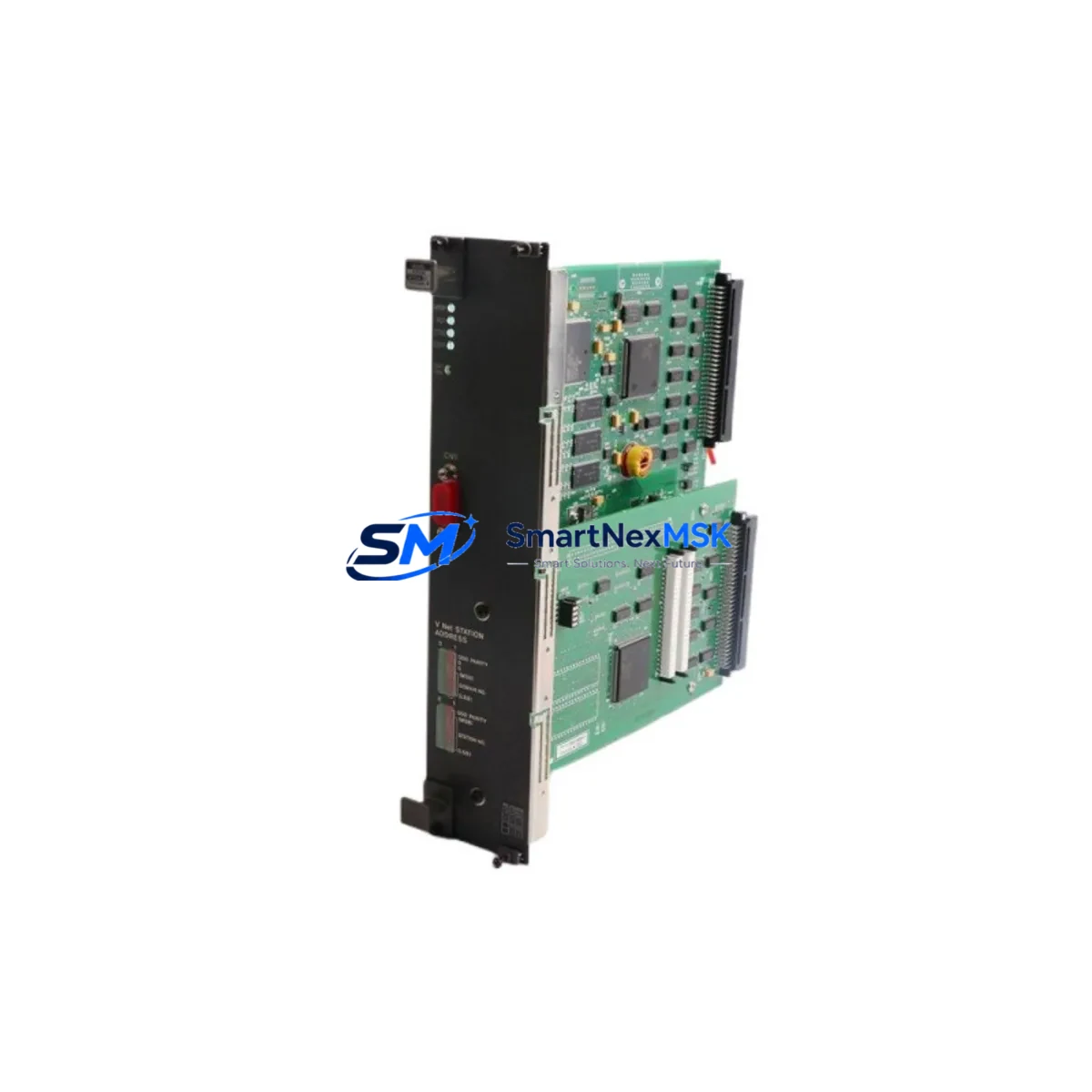
YOKOGAWA MRI-234*B Retrofit-Ready Power Supply for MRI Series Control Systems
The YOKOGAWA MRI-234*B is a retrofit-ready DC power supply module engineered for seamless integration into legacy MRI Series distributed control system (DCS) architectures. As original MRI-234*B units reach end-of-life and OEM supply chains dry up, plant engineers and system integrators face mounting pressure to source verified replacement modules that preserve existing wiring layouts, rack configurations, and program logic without triggering a full system overhaul. This module addresses that challenge directly — offering a drop-in compatible solution backed by pre-shipment functional testing and a 12-month warranty.
Whether you are managing a scheduled turnaround, responding to an unplanned failure, or executing a phased control system upgrade, the MRI-234*B provides the electrical and mechanical compatibility required to restore or extend the operational life of your MRI Series DCS installation with minimal downtime exposure.
Upgrade Compatibility Table
| Parameter | Details |
|---|---|
| Compatible Platform | YOKOGAWA MRI Series DCS |
| Module Type | DC Power Supply Module |
| Replaces / Supersedes | MRI-234*B (OEM discontinued) |
| Rack / Backplane Interface | MRI Series standard backplane slot — direct insertion, no adapter required |
| Terminal Wiring | Matches original MRI-234*B terminal layout; no rewiring required |
| Communication Compatibility | Transparent to DCS communication bus; no protocol reconfiguration needed |
| Installation Requirement | Standard MRI Series rack; confirm slot address assignment before insertion |
| Commissioning Focus | Verify output voltage, load capacity, and redundancy switchover behavior |
| Pre-Shipment Testing | Full functional burn-in and output verification performed before dispatch |
| Warranty | 12 Months — covers manufacturing defects and functional failure under normal operating conditions |
Retrofit Planning for Existing Automation Systems
Successful retrofit of the MRI-234*B into an operating plant environment requires systematic pre-work across several engineering disciplines. Before pulling the failed or aging module, the site team should document the existing power distribution topology within the control cabinet. The MRI Series DCS typically distributes 24 VDC across multiple I/O racks, and the MRI-234*B feeds one or more of these distribution rails. Confirm the rated output current against the actual connected load — including all active I/O modules, communication cards, and any field device loop power drawn through the rack.
Terminal block wiring on the MRI-234*B follows the standard MRI Series convention. Before disconnection, photograph or sketch the existing wiring and cross-reference against the original engineering drawings. In installations where the MRI-234*B operates in a redundant pair configuration alongside a second power supply module, verify that the redundancy diode or load-sharing circuit on the companion module is functional before relying on it during the swap window.
The MRI Series backplane accommodates a range of module types beyond the power supply, including analog input modules, analog output modules, digital I/O modules, and communication interface modules for HART, FOUNDATION Fieldbus, or PROFIBUS DP. When the MRI-234*B is removed, the backplane bus remains live if the redundant supply is active — exercise appropriate isolation procedures to protect adjacent modules such as the MRI-110 controller module or MRI-120 communication module from transient disturbances during the swap.
For sites running YOKOGAWA CENTUM VP or CENTUM CS 3000 as the supervisory layer, the DCS engineering station should be monitored during the replacement. The CENTUM system will log a module removal alarm; this is expected behavior and does not indicate a program fault. After reinsertion of the replacement MRI-234*B, confirm that the module address recognized by the controller matches the original slot assignment. In some MRI Series configurations, the module address is set via DIP switch on the module face — verify this against the original module or the system configuration database before powering up.
Field instruments connected through MRI Series I/O modules — including transmitters, control valves, and motor starters — should be placed in manual or safe-state hold during the power supply replacement window. Coordinate with the control room operator to freeze PID loops and inhibit interlock logic where appropriate. Once the replacement MRI-234*B is seated and powered, restore field devices in sequence, confirming signal integrity on each channel before releasing loops back to automatic control.
For sites that also need to address aging communication infrastructure, the MRI Series supports migration toward modern Ethernet-based supervisory networks. If the existing MRI-120 or equivalent communication module is approaching end-of-life, this retrofit window is an appropriate time to evaluate a parallel upgrade. Similarly, if the HMI graphics linked to this control loop are running on legacy YOKOGAWA HIS (Human Interface Station) hardware, the power supply replacement can be coordinated with an HMI refresh to minimize total outage events.
Downtime Control During System Migration
Minimizing unplanned downtime during a DCS power supply replacement is a function of preparation, sequencing, and verification discipline. The MRI-234*B replacement procedure, when properly planned, can be executed within a two-to-four-hour maintenance window in most MRI Series installations.
Begin by staging the replacement module at the control cabinet before the maintenance window opens. Confirm the module has passed pre-shipment testing and that the warranty documentation is on file. Prepare a rollback plan: if the replacement module does not initialize correctly, the original module (if still partially functional) or a second spare should be available on-site.
During the swap, maintain continuous communication between the field technician at the cabinet and the control room operator. Use a radio or intercom channel dedicated to the maintenance activity. The control room operator should monitor the CENTUM VP or CENTUM CS 3000 alarm summary in real time and call out any unexpected system responses immediately.
After the replacement MRI-234*B is installed and powered, perform a structured commissioning check: verify DC output voltage at the module terminals, confirm all downstream I/O modules have returned to normal status in the DCS, check that redundancy switchover logic is armed if applicable, and validate that all field device signals are reading correctly in the HMI. Document the as-found and as-left conditions for the maintenance record.
Original program logic stored in the MRI Series controller — including PID tuning parameters, interlock configurations, and sequence logic — is not affected by a power supply module replacement. The controller retains its program in non-volatile memory during the power interruption. However, any controller modules that lost power during the swap should be confirmed to have reloaded their runtime configuration correctly before returning the unit to automatic operation.
Retrofit Support FAQ
Q: Is the MRI-234*B a direct drop-in replacement for the original YOKOGAWA MRI-234*B module?
A: Yes. The replacement module matches the original MRI-234*B in form, fit, and function. It installs into the same MRI Series backplane slot, uses the same terminal wiring layout, and requires no modification to the existing rack, wiring, or DCS configuration.
Q: What commissioning steps are required after installing the replacement module?
A: After insertion, verify the module slot address matches the original DCS configuration, confirm DC output voltage at rated load, check that all downstream I/O modules have returned to active status in the CENTUM supervisory system, and validate field device signal integrity on all connected channels. If the module operates in a redundant pair, test the switchover function before returning to normal operation.
Q: How do I verify wiring compatibility before removing the original module?
A: Document the existing terminal connections by photograph or sketch before disconnection. The MRI-234*B replacement uses the same terminal numbering and polarity convention as the original module. Cross-reference against the original engineering drawings or the MRI Series hardware manual to confirm before reconnection.
Q: What does the 12-month warranty cover?
A: The 12-month warranty covers manufacturing defects and functional failure under normal operating conditions from the date of shipment. Each unit undergoes pre-shipment functional burn-in and output verification testing. Warranty claims are supported by our technical team — contact sales@smartnexmsk.com with the order reference and a description of the fault condition.
© 2026 SMARTNEXMSK. All rights reserved.
Original Source: https://smartnexmsk.com
Contact: sales@smartnexmsk.com | +86 18259474341


