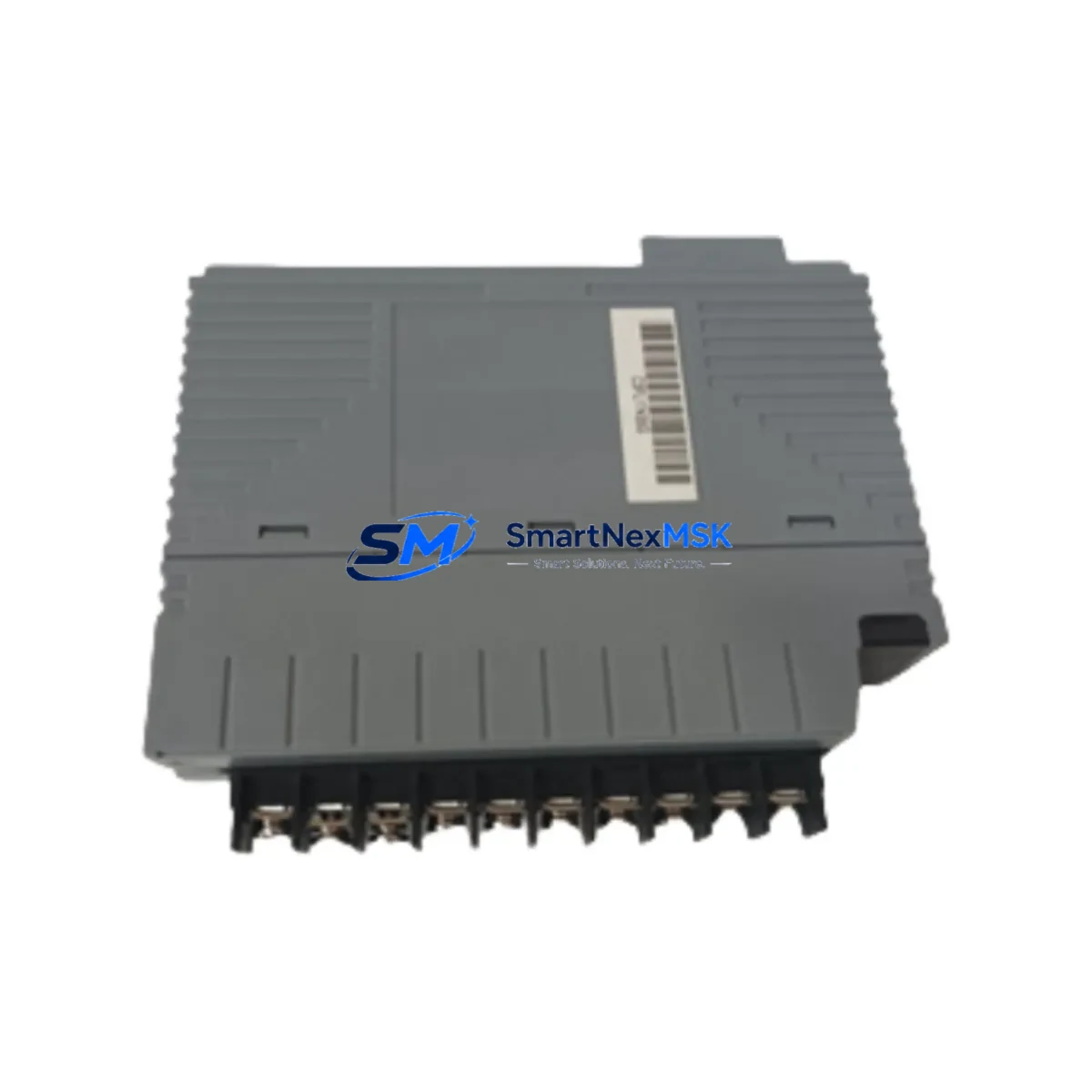
YOKOGAWA NFLC121-S00 Retrofit-Ready Foundation Fieldbus H1 Module for NFLC Series Control Systems
The YOKOGAWA NFLC121-S00 is a Foundation Fieldbus H1 (FF H1) communication module engineered for seamless integration into YOKOGAWA CENTUM VP and CS 3000 distributed control systems. As legacy NFLC-series fieldbus modules approach end-of-life or become increasingly difficult to source, the NFLC121-S00 represents the most direct, specification-matched replacement path available — minimizing engineering risk, reducing commissioning time, and protecting the integrity of existing control logic and HMI configurations.
This module is purpose-built for industrial environments where control continuity is non-negotiable. Whether you are managing a planned turnaround, responding to an unplanned failure, or executing a phased modernization of an aging fieldbus segment, the NFLC121-S00 delivers the electrical, mechanical, and protocol compatibility required to restore or upgrade your system with confidence.
Upgrade Compatibility Table
| Parameter | NFLC121-S00 Specification | Retrofit Notes |
|---|---|---|
| Communication Protocol | Foundation Fieldbus H1 (FF H1) | Direct protocol match with existing NFLC-series segments; no gateway required |
| Backplane Interface | YOKOGAWA NFLC-series node unit backplane | Plug-in compatible with existing node unit racks; verify slot addressing before installation |
| Power Supply Compatibility | Supplied via node unit backplane (24 VDC bus) | Confirm existing power supply (e.g., PW481 or equivalent) capacity covers added segment load |
| Terminal Wiring | Standard FF H1 twisted-pair, polarity-sensitive | Retain existing field cable terminations; verify shield grounding at one end only |
| Module Address | Configurable via CENTUM VP / CS 3000 engineering station | Re-assign node address in system builder; backup existing address map before swap |
| HMI / Graphic Compatibility | Full tag-level compatibility with CENTUM VP HIS | Existing HMI faceplates and trend displays remain valid; no graphic rebuild required |
| Program Logic Compatibility | Compatible with existing FCS function block logic | No control logic rewrite needed; verify function block assignments post-swap |
| Installation Form Factor | Standard NFLC-series module footprint | Direct mechanical fit; no panel modification or bracket adapter required |
| Replacement Scope | Supersedes discontinued NFLC-series FF H1 variants | Confirm firmware revision compatibility with FCS controller version |
| Warranty | 12-Month Warranty | Covers manufacturing defects; includes pre-shipment functional test documentation |
Retrofit Planning for Existing Automation Systems
A successful NFLC121-S00 retrofit begins well before the module arrives on-site. The first step is a thorough audit of the existing fieldbus segment: document all field devices connected to the affected FF H1 segment, record their device tags, physical addresses, and DD (Device Description) file versions. This information is critical when re-commissioning the segment after module replacement.
Power budget verification is essential. The NFLC121-S00 draws power from the node unit backplane, which is typically shared with other modules such as the NFLM series I/O modules, NFCP series controller cards, and NFIO analog and digital I/O modules. Before installation, calculate the total current draw across all populated slots and confirm the installed power supply — commonly a PW481 or PW482 unit — has sufficient headroom. Overloading the backplane bus is a leading cause of intermittent faults in retrofitted systems.
Terminal wiring for Foundation Fieldbus H1 is polarity-sensitive. When replacing the NFLC121-S00, label and photograph all existing field cable connections before disconnection. The FF H1 segment cable — typically a shielded twisted pair conforming to IEC 61158-2 — should be inspected for insulation integrity and correct termination resistance (100 Ω terminator at each physical end of the segment). If the existing segment uses a YOKOGAWA fieldbus power conditioner or segment coupler, verify its output voltage and ripple specifications remain within FF H1 tolerances.
For systems running CENTUM VP or CS 3000, the engineering station (ENG) must be used to update the hardware configuration in System Builder before the new module is brought online. Assign the correct node address, confirm the FCS (Field Control Station) recognizes the new module, and perform a download of the updated hardware configuration. Do not attempt to hot-swap the module without first placing the affected FCS in manual mode and notifying the control room operator — uncontrolled transitions can trigger interlock sequences or process alarms.
Communication link integrity should be verified using a YOKOGAWA-compatible FF H1 diagnostic tool or a third-party fieldbus analyzer. Check segment voltage (nominally 9–32 VDC at the device terminals), signal quality, and device response times before returning the segment to automatic control. If the system includes a YOKOGAWA YFGW410 or YFGW510 field wireless management station integrated with the fieldbus network, confirm that the wireless-to-wired gateway configuration is unaffected by the module swap.
For larger retrofit projects involving multiple fieldbus segments, it is common to also replace or upgrade associated NFCP controller cards, NFIO digital input/output modules, and NFLM series link modules in the same maintenance window. Coordinating these replacements reduces total downtime and avoids repeated partial shutdowns. If the project scope includes migration from an older CS 3000 platform to CENTUM VP, the NFLC121-S00 is fully supported in the CENTUM VP hardware environment, making it a viable bridge component during phased migration.
Downtime Control During System Migration
Minimizing unplanned downtime during a fieldbus module replacement requires a structured pre-work package. Before the maintenance window opens, prepare a module swap procedure that includes: a step-by-step wiring disconnection and reconnection sequence, a pre-defined FCS mode transition plan (Auto → Manual → Offline → Online), and a rollback procedure in case the replacement module does not initialize correctly.
Where the process permits, place all field devices on the affected FF H1 segment into manual or local control mode before disconnecting the NFLC121-S00. This prevents spurious output changes during the module swap. For critical loops — such as flow control, pressure regulation, or temperature management — coordinate with the process team to hold setpoints manually at the DCS operator station (HIS) during the transition period.
Once the NFLC121-S00 is installed and the FCS hardware configuration has been downloaded, bring the segment online incrementally: verify each field device communicates correctly, confirm its process variable (PV) reads accurately against a local gauge or independent transmitter, and return each loop to automatic control only after the operator confirms stable readings. This loop-by-loop commissioning approach is slower than a bulk restart but dramatically reduces the risk of a process upset caused by a misconfigured device or incorrect address assignment.
All NFLC121-S00 units supplied by SMARTNEXMSK undergo pre-shipment functional testing, including communication initialization, segment voltage output verification, and firmware version confirmation. Test documentation is available upon request. This pre-shipment validation reduces on-site commissioning time and provides a baseline for warranty claims if issues arise after installation.
Retrofit Support FAQ
Q1: Is the NFLC121-S00 a direct drop-in replacement for all NFLC-series FF H1 modules?
The NFLC121-S00 is mechanically and electrically compatible with the NFLC-series node unit backplane and supports the Foundation Fieldbus H1 protocol. However, firmware revision compatibility with your specific FCS controller version should be confirmed before installation. Contact our technical team with your FCS model and firmware version for a definitive compatibility assessment.
Q2: What wiring changes are required when installing the NFLC121-S00?
In most cases, no wiring changes are required. The existing FF H1 segment cable connects to the same terminal positions as the predecessor module. Verify polarity, confirm termination resistors are correctly placed at both physical ends of the segment, and inspect the shield grounding arrangement. If the existing installation used non-standard wiring practices, correct these during the replacement to ensure long-term signal integrity.
Q3: Can the NFLC121-S00 be used in a CENTUM VP system that was originally configured for CS 3000?
Yes. The NFLC121-S00 is supported in both CENTUM VP and CS 3000 environments. For systems migrated from CS 3000 to CENTUM VP, the module can be re-used in the new hardware environment provided the node address and FCS hardware configuration are updated in the CENTUM VP engineering station. Consult the YOKOGAWA migration guide for your specific platform version.
Q4: What does the 12-month warranty cover, and what documentation is provided?
The 12-month warranty covers manufacturing defects and functional failures under normal operating conditions. Each unit is shipped with a pre-shipment test report confirming communication initialization and segment voltage output. Warranty claims require the original invoice and a description of the failure mode. Replacement or repair is processed within the warranty period at no additional cost. Contact sales@smartnexmsk.com to initiate a warranty claim.
© 2026 SMARTNEXMSK. All rights reserved.
Original Source: https://smartnexmsk.com
Contact: sales@smartnexmsk.com | +86 18259474341


