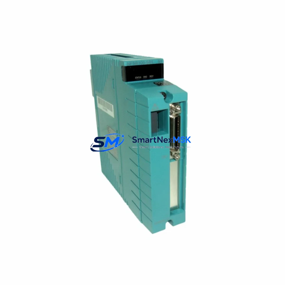
YOKOGAWA NFSB100-S01 Maintenance-Ready Spare for CENTUM VP Automation
The YOKOGAWA NFSB100-S01 is an original Vnet/IP Bus Repeater Module engineered for the CENTUM VP and CS 3000 Distributed Control System (DCS) platforms. In process industries — refining, petrochemical, power generation, and pharmaceutical manufacturing — the Vnet/IP communication backbone is mission-critical. A failed bus repeater can isolate entire field station clusters, triggering unplanned shutdowns and costly production losses. Stocking a verified NFSB100-S01 spare is a fundamental element of any responsible maintenance strategy for YOKOGAWA-based control architectures.
This unit is sourced as an original YOKOGAWA component, pre-shipment tested for electrical integrity and communication function, and supplied with a 12-month warranty. Whether you are executing a planned turnaround, responding to an emergency fault, or building out your critical spare inventory, the NFSB100-S01 is ready for immediate deployment into your CENTUM VP cabinet.
Spare Maintenance Table
| Parameter | Specification |
|---|---|
| Part Number / SKU | NFSB100-S01 |
| Brand | YOKOGAWA |
| Series / Platform | CENTUM VP / CS 3000 |
| Module Function | Vnet/IP Bus Repeater — extends and isolates Vnet/IP communication segments |
| Communication Protocol | Vnet/IP (YOKOGAWA proprietary Ethernet-based DCS network) |
| Compatible Systems | CENTUM VP R4.x / R5.x / R6.x; CS 3000 R3.x |
| Installation | DIN-rail or cabinet backplane mount; plug-in replacement |
| Power Supply | Supplied via system bus; no external power wiring required |
| Operating Temperature | 0 °C to 55 °C (32 °F to 131 °F) |
| Humidity | 5% to 95% RH, non-condensing |
| Country of Origin | Japan |
| Unit Weight | Approx. 200 g |
| Warranty | 12 Months — covers manufacturing defects and functional failure under normal operating conditions |
| Condition | Original YOKOGAWA; pre-shipment functional test completed |
| Shipping | ESD-safe packaging; global express delivery available |
| Maintenance Recommendation | Inspect bus repeater LEDs and segment continuity during every scheduled cabinet inspection cycle |
Maintenance Planning for Continuous Operation
When a maintenance or reliability engineer identifies a fault or degradation in the Vnet/IP communication segment, replacing the NFSB100-S01 bus repeater is rarely the only action required. A thorough site inspection should encompass the full communication and power chain to prevent repeat failures and confirm system integrity before returning to automatic control.
Begin with the YOKOGAWA AFV10D or AFV30D Field Control Station (FCS) power supply modules — bus repeater faults are frequently preceded by marginal supply voltage on the Vnet/IP segment. Verify that the NFCP100 or NFCP010 Vnet/IP coupler modules on adjacent segments are operating within specification, as a degraded coupler can stress the repeater and cause premature failure. Inspect the Vnet/IP optical fiber patch cables and RJ-45 copper segment cables for physical damage, bend radius violations, or connector oxidation — communication errors at the physical layer are a leading cause of repeater overload.
Check the YOKOGAWA PFCS100 or PFCS200 process field control station backplane for secure module seating and backplane connector integrity. During the same cabinet inspection, review the status of NFBU100 bus unit modules and any installed NFIO-series I/O modules connected downstream of the repeater — an I/O module with a shorted output can generate bus traffic anomalies that accelerate repeater wear. Confirm that YOKOGAWA CENTUM VP engineering workstation (EWS) communication to the affected FCS is fully restored after replacement and that no residual alarms remain in the system historian.
For sites running hybrid architectures, also inspect any YOKOGAWA STARDOM FCN/FCJ autonomous controllers or ProSafe-RS Safety Instrumented System (SIS) modules that share the same control room cabinet infrastructure — a bus fault event can mask secondary issues in adjacent safety loops. Finally, verify that UPS and cabinet cooling systems are functioning correctly; thermal stress is a primary accelerant of bus communication hardware degradation in long-running DCS installations.
Site Replacement Workflow
Step 1 — Fault Isolation: Use the CENTUM VP System View or HIS (Human Interface Station) alarm summary to confirm which Vnet/IP segment has lost communication. Cross-reference with the FCS LED status on the NFSB100-S01 unit — a solid red or extinguished link LED confirms the repeater as the fault source.
Step 2 — Safe Removal: Notify the control room operator and place the affected FCS in manual or backup control mode per your site MOC (Management of Change) procedure. The NFSB100-S01 is a hot-swap-capable module in most CENTUM VP configurations; confirm your system revision supports online replacement before proceeding without a full shutdown.
Step 3 — Spare Installation: Remove the faulty unit, insert the replacement NFSB100-S01, and confirm secure backplane engagement. The module performs automatic self-initialization on power-up — no manual parameter download is required for standard bus repeater replacement.
Step 4 — Communication Verification: Monitor the Vnet/IP segment status in CENTUM VP System View for 3–5 minutes post-replacement. Confirm all downstream FCS nodes and I/O modules return to normal communication status. Clear any latched alarms and document the replacement in your CMMS (Computerized Maintenance Management System).
Step 5 — Spare Replenishment: Immediately initiate a purchase order for a replacement NFSB100-S01 to restore your critical spare inventory. For high-availability sites, a minimum of two units on-hand is recommended given the lead time variability for YOKOGAWA DCS communication hardware.
Spare Parts Support FAQ
Q1: Is the NFSB100-S01 compatible with both CENTUM VP and CS 3000 systems?
Yes. The NFSB100-S01 is designed for the Vnet/IP communication architecture shared by CENTUM VP (all revisions) and CS 3000 R3.x platforms. Always confirm your system firmware revision against YOKOGAWA’s compatibility matrix before installation, particularly for CS 3000 sites that have not been migrated to CENTUM VP.
Q2: What pre-shipment testing is performed on this spare?
Each NFSB100-S01 unit undergoes electrical continuity verification, power-on self-test, and communication port integrity checks prior to dispatch. Units are packed in ESD-safe anti-static bags with foam cushioning to prevent transit damage. A test report is available upon request for quality-critical procurement processes.
Q3: How should the NFSB100-S01 be stored as a long-term spare?
Store in a climate-controlled environment at 10–40 °C with relative humidity below 70%, away from direct sunlight and electromagnetic interference sources. Retain the original ESD packaging. Perform a visual inspection and power-on test annually if the unit remains in storage beyond 24 months. Capacitor aging on long-stored electronics can affect performance — units stored beyond 5 years should be bench-tested before deployment.
Q4: What does the 12-month warranty cover, and what is the claims process?
The 12-month warranty covers manufacturing defects and functional failure under normal operating conditions from the date of shipment. It does not cover damage resulting from incorrect installation, overvoltage events, or physical mishandling. To initiate a warranty claim, contact our support team with your order number, a description of the fault, and photographic evidence of the failed unit. Replacement or repair will be processed within the agreed service timeline.
© 2026 SMARTNEXMSK. All rights reserved.
Original Source: https://smartnexmsk.com
Contact: sales@smartnexmsk.com | +86 18259474341


