YOKOGAWA PS35*A Retrofit-Ready DCS Power Supply for Centum VP/CS3000 Control Systems
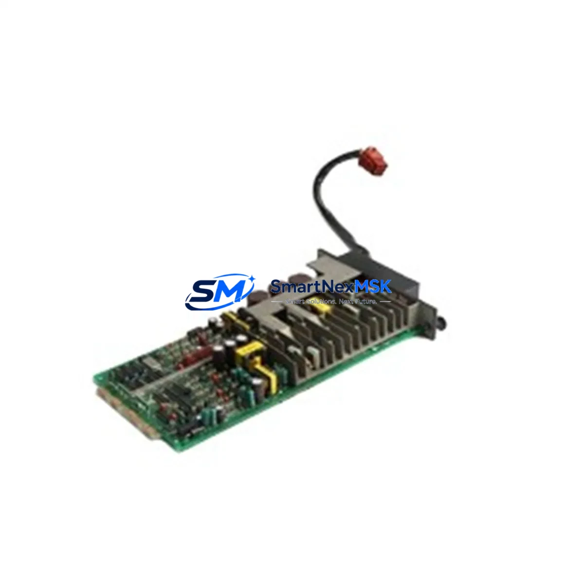
The YOKOGAWA PS35*A is a rack-mounted DC power supply module engineered for seamless integration into YOKOGAWA Centum VP and CS3000 distributed control system (DCS) architectures. As legacy Centum CS3000 installations approach end-of-life and plant operators accelerate migration to Centum VP platforms, the PS35*A serves as a critical retrofit component — enabling power infrastructure continuity without requiring full cabinet redesign or backplane replacement. Whether you are executing a phased upgrade, restoring a failed power rail, or consolidating spare parts inventory ahead of a planned shutdown, the PS35*A delivers the electrical stability and form-factor compatibility that industrial control engineers demand.
Sourced directly from verified supply channels and subject to pre-shipment functional testing, each PS35*A unit shipped by SMARTNEXMSK is backed by a 12-month warranty covering manufacturing defects and operational failures under normal DCS operating conditions. Our inventory is maintained to support urgent replacement scenarios, with same-week dispatch available for in-stock units.
Upgrade Compatibility Table
| Parameter | Details |
|---|---|
| Compatible Platforms | YOKOGAWA Centum VP, Centum CS3000, Centum CS 1000 |
| Module Type | DCS Rack Power Supply Module |
| Replaces / Upgrades | PS35*A (same SKU, drop-in); compatible with legacy PS32*A and PS33*A power slots in select rack configurations |
| Backplane Interface | Standard YOKOGAWA DCS backplane bus connector; verify rack generation (RIO, ESB, ER Bus) before installation |
| Installation Requirement | Power-off installation required; confirm rack slot assignment per engineering drawing |
| Communication Compatibility | No direct communication role; supports field controller nodes (FCN, FCJ, PFCD) via stable DC rail |
| Replacement Recommendation | Replace in pairs where redundant power configuration is active; verify load balance after swap |
| Commissioning Focus | Output voltage verification, load test under live rack conditions, alarm reset on DCS HMI |
| Warranty | 12 months from shipment date — covers manufacturing defects and operational failure under normal DCS conditions |
Retrofit Planning for Existing Automation Systems
Replacing a power supply module in an operating DCS environment requires careful pre-work to avoid unplanned process interruptions. Before removing the existing PS35*A or its predecessor, engineers should audit the full rack assembly. In a typical Centum VP cabinet, the power module shares the enclosure with field control units such as the FCN-RTU or PFCD controller card, I/O modules including AI, AO, DI, and DO cards, and communication interface modules handling FOUNDATION Fieldbus, HART, or Modbus RTU signals. Each of these components draws from the common DC bus supplied by the PS35*A, making power rail stability a prerequisite for uninterrupted field signal acquisition.
During retrofit planning, confirm the total current draw of all installed modules against the PS35*A rated output capacity. In high-density racks where additional AI843 analog input modules or DI841 digital input modules have been added since original commissioning, the power budget may have shifted. If the rack also hosts an ER Bus coupler or ESB bus interface module for remote I/O expansion, include those loads in the calculation. Where redundant power supply slots are available — a common configuration in Centum VP safety-critical applications — plan to replace one unit at a time, verifying output stability before proceeding to the second module.
Terminal wiring on the incoming AC side must be inspected for insulation condition and torque compliance before the new PS35*A is energized. In older CS3000 installations, terminal blocks may show signs of thermal stress from years of continuous operation. Replacing the terminal block assembly alongside the power module is recommended practice during planned maintenance windows. Confirm that the replacement module’s output connector seats fully into the backplane without mechanical interference — a common issue when rack guide rails have deformed over time.
For sites migrating from CS3000 to Centum VP, the PS35*A is often retained as part of a hybrid architecture where legacy I/O sub-systems remain in service while the supervisory layer is upgraded. In this scenario, the power module must support both the legacy Centum CS3000 field control station (FCS) and any newly installed Centum VP field control units sharing the same cabinet. Verify module address assignments and ensure the DCS engineering tool — YOKOGAWA’s CENTUM VP Engineering Environment — reflects the updated hardware configuration before downloading revised control logic. HMI faceplates referencing power supply status tags should also be reviewed to confirm alarm thresholds remain valid after the hardware swap.
Downtime Control During System Migration
Minimizing process downtime during a DCS power supply replacement begins with preparation, not execution. The most effective approach is to pre-stage the replacement PS35*A in the control room, perform a visual and dimensional check against the installed unit, and confirm firmware or hardware revision compatibility with the site’s DCS version. Where the process cannot tolerate a full power interruption, coordinate with operations to identify a maintenance window aligned with a natural process pause — batch changeover, scheduled cleaning cycle, or shift handover.
Before de-energizing the rack, export a full backup of the control logic from the field control station using the CENTUM VP engineering workstation. Save the project file with a timestamped revision label. If the site uses a historian such as YOKOGAWA Exaquantum or a third-party OPC DA/UA server, verify that the historian client will tolerate a brief communication gap without generating spurious alarms or data gaps that require manual reconciliation.
During the swap, keep the replacement window to under 30 minutes by having all tools, torque specifications, and wiring diagrams on hand before the rack is de-energized. After installing the PS35*A, restore power incrementally — energize the power module first, verify DC output voltage at the backplane test points, then allow the field control station to complete its self-diagnostic sequence before re-enabling field I/O scanning. Confirm that all analog input and output modules resume normal operation and that no latched alarms remain on the DCS operator station. Document the replacement in the site’s maintenance management system with the new module’s serial number and installation date to support future warranty claims and audit trails.
Retrofit Support FAQ
Q1: Is the PS35*A a direct drop-in replacement for units currently installed in my CS3000 rack?
In the majority of CS3000 and Centum VP rack configurations, the PS35*A is a direct mechanical and electrical replacement. Confirm the rack generation (standard, high-density, or extended) and the power slot designation in your site engineering drawings before installation. Contact our technical team with your rack model number if you require pre-shipment compatibility confirmation.
Q2: What commissioning checks are required after installing the replacement PS35*A?
After installation, verify DC output voltage at the backplane test points against the specification in the YOKOGAWA hardware manual. Perform a load test by confirming all installed I/O modules and communication cards power up without fault. Reset any power-related alarms on the DCS operator station and confirm that field signal values are within expected ranges before returning the loop to automatic control.
Q3: Can the PS35*A support a rack that has been expanded with additional I/O modules since original commissioning?
The PS35*A has a defined rated output current. If additional AI, AO, DI, or DO modules have been added to the rack since the original power budget was calculated, verify that total current draw remains within the module’s rated capacity. Where the budget is marginal, consider upgrading to a higher-capacity power supply or redistributing I/O modules across multiple racks.
Q4: What does the 12-month warranty cover, and how do I initiate a claim?
The 12-month warranty covers manufacturing defects and operational failures occurring under normal DCS operating conditions — correct supply voltage, ambient temperature within specification, and proper installation per YOKOGAWA guidelines. To initiate a claim, contact sales@smartnexmsk.com with your order number, module serial number, and a description of the fault. Our team will arrange inspection and replacement or repair within the warranty period.
© 2026 SMARTNEXMSK. All rights reserved.
Original Source: https://smartnexmsk.com
Contact: sales@smartnexmsk.com | +86 18259474341


