YOKOGAWA SB401-11 Maintenance-Ready Spare for CENTUM VP Automation
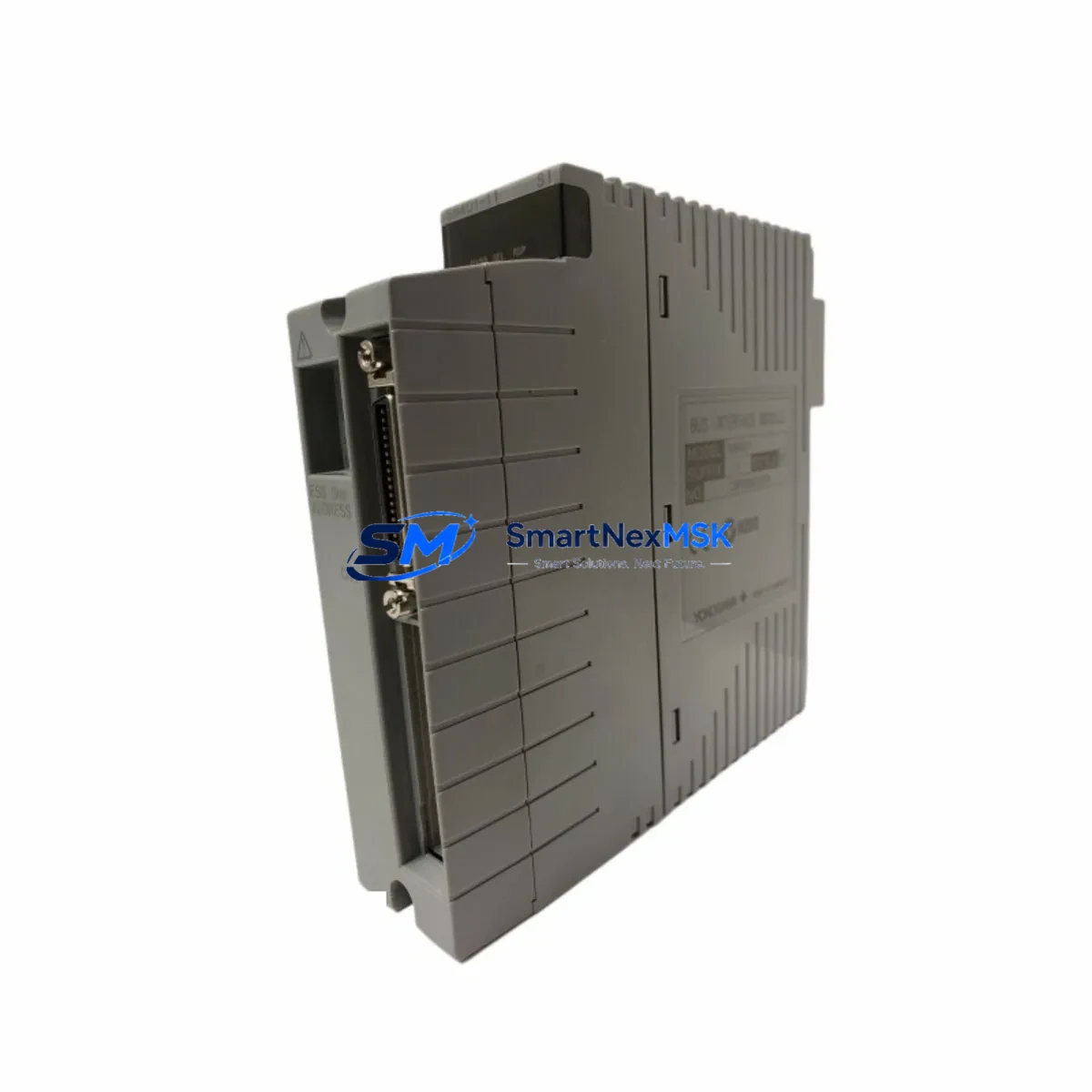
The YOKOGAWA SB401-11 is an original bus interface module engineered for deployment within CENTUM VP and CS 3000 distributed control systems. For maintenance engineers managing aging DCS infrastructure, this module represents a critical spare that directly impacts system uptime and process continuity. Unplanned failure of a bus interface module can cascade into full I/O segment loss, making rapid, verified replacement essential to minimizing production downtime. Sourcing a tested, original SB401-11 from a reliable supplier with documented 12-month warranty coverage is the foundation of any responsible spare parts strategy for YOKOGAWA-based control systems.
Spare Maintenance Table
| Parameter | Specification |
|---|---|
| Part Number / SKU | SB401-11 |
| Brand | YOKOGAWA |
| Series | CENTUM VP / CS 3000 |
| Module Type | Bus Interface Module |
| Communication Bus | V-net / ER Bus (YOKOGAWA proprietary) |
| Compatibility | CENTUM VP R4.x–R6.x, CS 3000 R3.x field control stations |
| Mounting | Standard YOKOGAWA FCS node unit backplane slot |
| Power Supply | Supplied via backplane (no external wiring required) |
| Operating Temperature | 0°C to 55°C (32°F to 131°F) |
| Humidity | 10% to 90% RH, non-condensing |
| Origin | Japan |
| Condition | Original, tested before shipment |
| Warranty | 12 Months from date of shipment |
| Lead Time | In stock — ships within 2 business days |
| Application | Process automation, oil & gas, chemical, power generation, pulp & paper |
Maintenance Planning for Continuous Operation
When a maintenance or procurement engineer schedules replacement of the SB401-11 bus interface module, the scope of inspection should extend beyond the module itself. A bus interface failure is rarely isolated — it often signals stress on adjacent components within the same field control station (FCS) node. A thorough site assessment should include the following areas:
Power and Backplane Integrity: Inspect the PW481 or PW482 power supply module feeding the FCS node. Degraded DC rail voltage is a leading cause of bus interface instability. Verify the backplane connector pins for oxidation or mechanical wear before seating the replacement SB401-11.
I/O Module Verification: After restoring bus communication, validate all connected I/O modules — including AAI141 analog input, AAI543 analog output, and ADV151 digital input modules — to confirm signal integrity has not been compromised during the fault period. Any module showing abnormal LED status should be flagged for swap-out.
Communication and Network Modules: Check the ESB401 or ESB105 Ethernet communication modules within the same cabinet. A bus fault can generate error logs that persist in the network layer even after the hardware is replaced. Clear fault histories and verify V-net segment health using the CENTUM VP engineering workstation.
Relay and Terminal Blocks: Inspect field-side terminal blocks and intermediate relay modules connected to the I/O cards downstream of the SB401-11. Loose terminations or failed relay coils can produce intermittent signals that are misdiagnosed as bus-level faults.
Signal Isolation and Protection: For loops connected to hazardous area instruments, verify that Zener barriers or galvanic isolators in the marshalling cabinet remain within specification. A bus interface replacement is an ideal checkpoint to audit signal isolation integrity across the entire FCS segment.
HMI and Engineering Station Connectivity: After module replacement, confirm that the CENTUM VP HMI stations and the HIS (Human Interface Station) correctly re-establish communication with the restored FCS node. Verify that all faceplates, trends, and alarm displays reflect live data before returning the loop to automatic control.
Fuse and Circuit Protection: Check panel-mounted fuses and MCBs protecting the FCS cabinet power distribution. A blown fuse upstream of the power supply module is a common root cause of bus interface module failures that goes undetected without a full cabinet inspection.
Maintaining a minimum of one SB401-11 as a cold-standby spare — alongside spares for the PW481 power supply and at least one each of the primary I/O module types — is the recommended strategy for facilities operating CENTUM VP systems beyond their original design life.
Site Replacement Workflow
Step 1 — Pre-Replacement Verification: Confirm the failed module’s part number (SB401-11) against the FCS node slot assignment in the CENTUM VP system builder. Cross-reference with the plant’s instrument index to identify all I/O points served by this bus segment.
Step 2 — Safe Isolation: Place all affected control loops in manual mode at the HIS. Notify the control room and obtain a permit-to-work before opening the FCS cabinet. Observe ESD precautions — the SB401-11 is sensitive to electrostatic discharge.
Step 3 — Module Swap: Remove the failed SB401-11 by releasing the module locking lever and sliding it clear of the backplane. Insert the replacement module firmly until the connector seats fully. The module is hot-swappable in most CENTUM VP configurations, but confirm with your system revision documentation before proceeding without a full node restart.
Step 4 — System Restoration: Monitor the FCS node status on the CENTUM VP engineering workstation. The replacement module should self-configure from the node’s resident database within 60–90 seconds. Verify all I/O points return to normal scan status before returning loops to automatic.
Step 5 — Post-Replacement Documentation: Record the replacement in the plant’s maintenance management system (CMMS), including the new module’s serial number and the date of installation. Update the spare parts inventory to trigger reorder of a replacement SB401-11 for the cold-standby stock.
This workflow is compatible with both direct replacement of legacy CS 3000 bus interface modules and migration scenarios where older node hardware is being upgraded to current CENTUM VP R6 specifications, ensuring system compatibility is maintained without requiring a full FCS reconfiguration.
Spare Parts Support FAQ
Q1: Is the SB401-11 compatible with both CENTUM VP and CS 3000 systems?
Yes. The SB401-11 is designed for use across YOKOGAWA CENTUM VP (R4.x through R6.x) and CS 3000 (R3.x) field control station platforms. Always verify the specific FCS node type and software revision against YOKOGAWA’s hardware compatibility matrix before installation to confirm slot and firmware alignment.
Q2: What does the 12-month warranty cover?
The 12-month warranty covers manufacturing defects and functional failures under normal operating conditions from the date of shipment. Each SB401-11 unit is tested for communication integrity and electrical function prior to dispatch. Warranty claims are supported with replacement or refund, subject to inspection of the returned unit.
Q3: How quickly can the SB401-11 be shipped, and what testing is performed before dispatch?
Units in stock ship within 2 business days. Pre-shipment testing includes power-on functional verification, bus communication handshake testing, and visual inspection for connector and PCB integrity. A test report is available upon request for critical plant applications.
Q4: What is the recommended spare parts holding strategy for CENTUM VP systems?
For facilities with continuous process requirements, we recommend maintaining at least one SB401-11 bus interface module as a cold-standby spare per FCS node type in service. This should be complemented by spares for the primary power supply module, at least two I/O module types per installed card family, and one communication module per network segment. A documented annual spare parts audit aligned with planned shutdown schedules is the most effective way to prevent unplanned downtime caused by obsolete or end-of-life DCS hardware.
© 2026 SMARTNEXMSK. All rights reserved.
Original Source: https://smartnexmsk.com
Contact: sales@smartnexmsk.com | +86 18259474341


