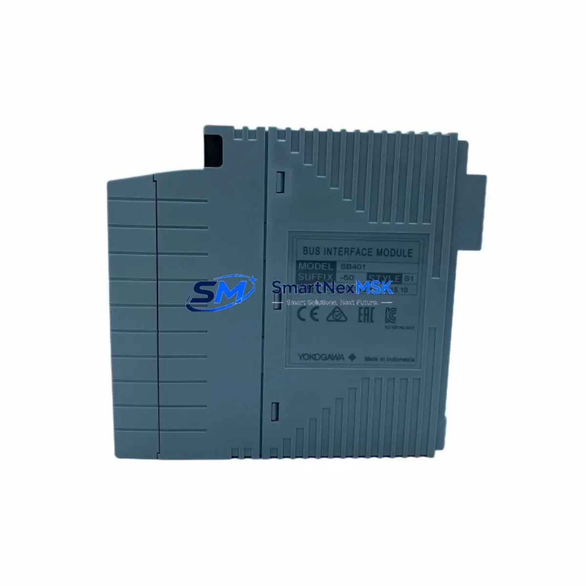
YOKOGAWA SB401-50 Maintenance-Ready Spare for FA-M3 Automation
The YOKOGAWA SB401-50 is an original bus interface slave module designed for the FA-M3 and STARDOM distributed control architectures. In industrial environments where unplanned downtime translates directly into production loss, maintaining a verified spare of the SB401-50 in your parts inventory is a fundamental risk-control measure. This module serves as the communication bridge between the FA-M3 main CPU rack and remote I/O sub-racks, making it a single point of failure that demands proactive spare management. Every unit supplied by SMARTNEXMSK is sourced as an original YOKOGAWA component, subjected to pre-shipment functional testing, and backed by a 12-month warranty — giving maintenance engineers and procurement teams the confidence to deploy without hesitation.
Whether you are executing a planned shutdown inspection, responding to a bus communication fault alarm, or building out a critical-spares inventory for an aging FA-M3 system, the SB401-50 is a direct, plug-compatible replacement that requires no firmware modification or hardware reconfiguration when substituting a like-for-like unit. Its compact form factor and standardized bus connector ensure seamless integration into existing sub-rack assemblies, minimising the skill requirement for field replacement and reducing mean time to repair (MTTR) to the shortest possible window.
Spare Maintenance Table
| Parameter | Specification / Detail |
|---|---|
| SKU / Part Number | SB401-50 |
| Brand | YOKOGAWA |
| Series | FA-M3 / STARDOM |
| Module Type | Bus Interface Slave Module |
| Function | Remote I/O sub-rack bus communication interface |
| Compatibility | FA-M3 R3.x / STARDOM FCN / FCJ controller racks |
| Bus Standard | YOKOGAWA proprietary FA-M3 expansion bus |
| Installation | Direct slot insertion into FA-M3 sub-rack base unit |
| Operating Temperature | 0 °C to 55 °C (standard industrial panel environment) |
| Origin | Japan |
| Condition | Original, new or refurbished-to-spec; pre-shipment tested |
| Warranty | 12 Months — covers functional defects under normal operating conditions |
| Lead Time | In-stock units ship within 3–5 business days; long-term supply available |
| Maintenance Recommendation | Inspect bus connector pins and rack slot contacts during every planned shutdown; replace if communication error codes persist after cleaning |
Maintenance Planning for Continuous Operation
A bus communication fault on the SB401-50 rarely occurs in isolation. When a maintenance engineer investigates an FA-M3 sub-rack communication alarm, the diagnostic workflow should extend beyond the slave module itself. The power supply module feeding the sub-rack — typically a YOKOGAWA PW481 or PW482 series unit — must be verified for stable output voltage, as voltage sag is a common root cause of intermittent bus errors that are incorrectly attributed to the interface module. Similarly, the corresponding bus interface master module installed in the CPU rack should be inspected and, if available, swapped with a known-good spare to isolate the fault to the slave side.
I/O modules seated in the same sub-rack — including digital input modules such as the ADV151 or ADV161, digital output modules such as the ADV551, and analog input modules such as the AAI141 — should be reseated and checked for status LED indications during the fault investigation. A loose module in the same rack can cause bus contention that mimics a failed SB401-50. Terminal blocks and field wiring connected to those I/O modules should also be inspected for loose terminations, which can introduce ground loops or signal noise that stresses the bus.
For sites running STARDOM FCN or FCJ controllers in conjunction with FA-M3 remote I/O, the communication module on the controller side — such as the NX-D15W Ethernet communication module — should be included in the inspection checklist. If the system uses HART or FOUNDATION Fieldbus signal isolators between field instruments and the I/O modules, those isolators should be tested for correct loop current output, as degraded isolators can cause erratic process values that trigger nuisance alarms and complicate fault isolation. Fuse holders and miniature circuit breakers in the control cabinet supplying the sub-rack should be checked for continuity and thermal discolouration. Finally, any HMI or SCADA workstation displaying the bus fault should have its OPC or Modbus communication driver logs reviewed to confirm whether the fault is a genuine hardware event or a software timeout.
Building a structured spare-parts kit around the SB401-50 — including at minimum one spare power supply module, one spare bus master module, and a set of replacement terminal blocks — is the most cost-effective strategy for reducing unplanned downtime on FA-M3 systems that are beyond their original support lifecycle.
Site Replacement Workflow
Step 1 — Preparation: Before removing the faulty SB401-50, record the sub-rack slot position, note all active I/O module addresses in that rack, and confirm that the CPU has been placed in STOP mode or that the process is in a safe hold state. Download or photograph the current I/O configuration from the engineering workstation.
Step 2 — Removal: Power down the sub-rack using the dedicated rack power switch (do not remove the main cabinet breaker unless required by site safety procedures). Extract the SB401-50 by releasing the module locking lever and sliding it clear of the bus connector. Inspect the connector pins for corrosion or mechanical damage.
Step 3 — Installation: Insert the replacement SB401-50 into the same slot, ensuring the bus connector is fully seated and the locking lever is engaged. Restore sub-rack power and observe the module status LED — a solid green indication confirms successful bus initialisation.
Step 4 — Verification: From the engineering workstation or HMI, confirm that all I/O modules in the sub-rack are communicating normally and that no bus error codes remain active. Perform a short functional test of critical I/O points before returning the system to automatic operation.
Step 5 — Documentation: Log the replacement in the site maintenance management system (CMMS), record the serial number of the replaced module, and update the spare-parts inventory to trigger reorder of a replacement spare unit.
This workflow is compatible with both like-for-like replacement of a failed SB401-50 and proactive replacement during planned maintenance intervals, and it applies equally to legacy FA-M3 R3 installations and newer STARDOM-integrated architectures.
Spare Parts Support FAQ
Q1: Is the SB401-50 still available as a new original part, or only as refurbished stock?
SMARTNEXMSK maintains both new original and refurbished-to-specification units. All refurbished units undergo full functional testing on FA-M3-compatible test rigs before shipment. The 12-month warranty applies equally to both conditions. Availability is confirmed at the time of enquiry.
Q2: How do I verify compatibility with my specific FA-M3 rack revision before ordering?
Provide your CPU module part number and sub-rack base unit model when placing your enquiry. Our technical team will cross-reference the hardware revision matrix to confirm direct compatibility. In most cases, the SB401-50 is compatible across all FA-M3 sub-rack generations without modification.
Q3: What pre-shipment testing is performed on each SB401-50 unit?
Each unit is powered up and inserted into an FA-M3-compatible test rack. Bus initialisation, LED status indication, and communication handshake with a master module are verified. Units that fail any test stage are quarantined and not shipped. A test report is available upon request for critical-infrastructure procurement.
Q4: Can SMARTNEXMSK support long-term supply agreements for SB401-50 and related FA-M3 components?
Yes. For customers managing extended FA-M3 system lifecycles — particularly in industries such as oil and gas, chemicals, power generation, and water treatment — we offer long-term supply agreements with reserved stock allocation, priority fulfilment, and consolidated shipment scheduling. Contact our sales team to discuss a tailored spare-parts support programme.
© 2026 SMARTNEXMSK. All rights reserved.
Original Source: https://smartnexmsk.com
Contact: sales@smartnexmsk.com | +86 18259474341


