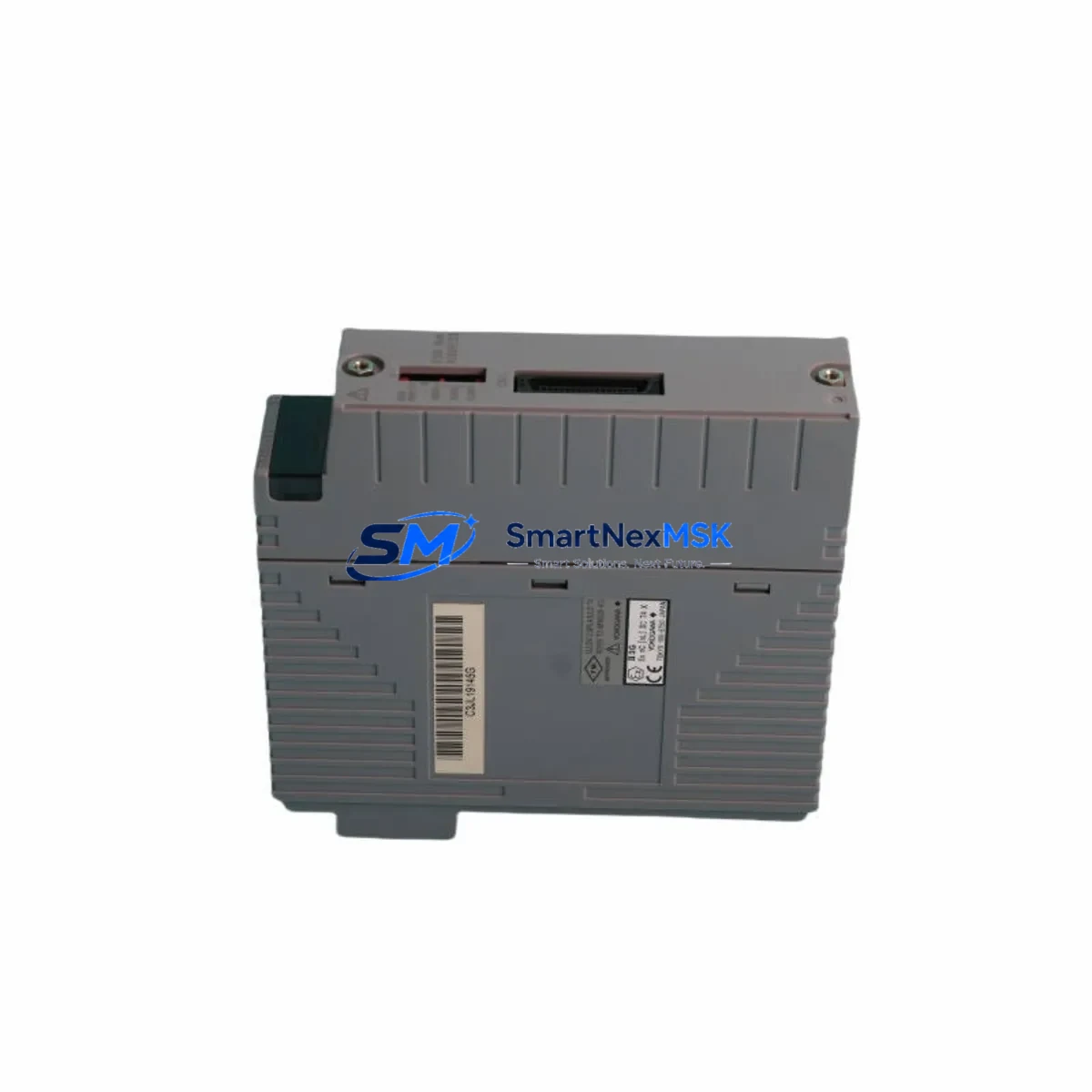
Yokogawa SDV531-S33 S2 Spare for CENTUM VP Automation
The Yokogawa SDV531-S33 S2 is a 32-channel digital output module designed for the CENTUM VP distributed control system — one of the most widely deployed DCS platforms in refining, petrochemical, power generation, and continuous process industries. As a maintenance-ready original spare, the SDV531-S33 S2 is engineered to deliver direct drop-in replacement capability, minimizing unplanned downtime and restoring control loop integrity with zero configuration overhead.
For maintenance engineers managing aging CENTUM VP installations, sourcing a verified original SDV531-S33 S2 is a critical step in any corrective or preventive maintenance plan. This module interfaces directly with the CENTUM VP field control station (FCS) backplane, supporting 24 VDC digital output signals to field devices including solenoid valves, motor starters, relay coils, and indicator lamps. Its solid-state output architecture reduces contact wear and extends service intervals compared to relay-based alternatives.
Procurement engineers and reliability teams operating CENTUM VP systems should maintain at least one SDV531-S33 S2 in their critical spare inventory. Module failure in a 32-channel DO card can simultaneously affect multiple control loops, triggering process shutdowns or safety system responses. Having a tested, pre-verified replacement on the shelf reduces mean time to repair (MTTR) from days to under an hour.
Each unit supplied by SMARTNEXMSK undergoes pre-shipment functional verification, is packaged in anti-static ESD-safe materials, and is backed by a 12-month warranty. Long-term supply continuity is supported for legacy CENTUM VP systems, including discontinued or hard-to-source variants.
Spare Maintenance Table
| Parameter | Specification |
|---|---|
| Model / SKU | SDV531-S33 S2 |
| Brand | Yokogawa Electric Corporation |
| Series | CENTUM VP (Field Control Station) |
| Module Type | 32-Channel Digital Output (DO) Module |
| Output Signal | 24 VDC Digital Output, Sink/Source configurable |
| Channel Count | 32 channels per module |
| Backplane Interface | CENTUM VP FCS I/O Bus (direct slot insertion) |
| Isolation | Optical isolation between field and system bus |
| Operating Temperature | 0°C to 55°C (standard industrial environment) |
| Mounting | DIN-rail / FCS I/O nest slot |
| Origin | Japan |
| Compatibility | CENTUM VP R4.xx / R5.xx / R6.xx FCS configurations |
| Replacement Scope | Direct replacement for SDV531-S33 S2; verify nest slot assignment in FCS builder |
| Maintenance Recommendation | Inspect output wiring, terminal blocks, and field device continuity before hot-swap |
| Warranty | 12 Months — covers manufacturing defects and functional failure under normal operating conditions |
| Pre-Shipment Test | Functional output verification on all 32 channels |
| Packaging | ESD-safe anti-static bag, foam-padded carton |
Maintenance Planning for Continuous Operation
When replacing the SDV531-S33 S2 in a CENTUM VP field control station, a thorough inspection of the surrounding I/O nest and control cabinet is essential to prevent repeat failures and ensure system stability. Maintenance engineers should treat this replacement as an opportunity for a broader cabinet health check.
Begin by verifying the 24 VDC power supply module feeding the I/O nest — a degraded power supply is a common root cause of DO module failure. Check output voltage under load and inspect for ripple or voltage sag. If the FCS uses a redundant power supply pair such as the Yokogawa PW481 or equivalent, confirm both units are operating within spec and that the changeover relay is functional.
Inspect the terminal block assemblies (e.g., Yokogawa TB series or equivalent marshalling terminals) connected to the SDV531-S33 S2 output channels. Loose terminations, corroded contacts, or overheated terminal blocks are frequent contributors to intermittent DO faults. Torque all terminals to specification and replace any discolored or deformed blocks.
Review the field wiring continuity for all 32 output channels. Broken field cables, shorted solenoid coils, or failed motor starter coils can cause overcurrent conditions that damage the DO module. Use a loop tester or multimeter to verify each field device load before energizing the replacement module.
If the CENTUM VP FCS also houses digital input modules such as the SDV541 or SDV521 series, inspect their status LEDs and channel diagnostics in the CENTUM VP HIS (Human Interface Station) engineering workspace. A failing DI module in the same nest can indicate a shared power or grounding issue affecting the entire I/O rack.
For systems with analog output modules (e.g., SAV144 or AAV141 series) in adjacent slots, verify that analog signal integrity has not been compromised by electrical noise introduced during the fault event. Signal isolators or barriers in the marshalling cabinet should be inspected and tested.
Communication modules such as the ACF11 (V-net/IP coupler) or ESB bus coupler connecting the FCS to the CENTUM VP control network should be checked for link status and error counters after any I/O module replacement. A module swap that causes a brief bus interruption can leave latent communication errors that affect historian data or alarm management.
Finally, review the FCS builder configuration in CENTUM VP Engineering to confirm the replacement SDV531-S33 S2 is assigned to the correct nest slot and that all 32 channel tags are mapped correctly. Download the configuration to the FCS and perform a channel-by-channel output test before returning the system to automatic control.
Site Replacement Workflow
Step 1 — Preparation: Obtain the FCS I/O nest layout drawing and identify the slot number of the failed SDV531-S33 S2. Confirm the replacement module part number matches exactly, including the suffix (S33 S2). Notify the control room operator and obtain a work permit if required by site safety procedures.
Step 2 — Safe State: Place all 32 output channels in a safe state via the CENTUM VP HIS operator console. For critical outputs (e.g., ESD-linked solenoids), coordinate with the process safety team before de-energizing. If the FCS supports hot-swap for this module type, confirm the procedure in the CENTUM VP hardware manual before proceeding.
Step 3 — Module Removal: Disconnect field wiring from the terminal block or marshalling panel. Label all wires before removal. Extract the SDV531-S33 S2 from the I/O nest by releasing the module locking lever. Inspect the backplane connector for bent pins or contamination.
Step 4 — Module Installation: Insert the replacement SDV531-S33 S2 into the correct nest slot. Ensure the module is fully seated and the locking lever is engaged. Reconnect field wiring per the as-built drawings. Verify terminal torque.
Step 5 — Commissioning: From the CENTUM VP HIS, confirm the module is recognized by the FCS and all 32 channel tags are online. Perform a forced output test on each channel to verify field device response. Clear any latched alarms and return outputs to automatic control. Document the replacement in the site maintenance management system (CMMS).
This workflow applies equally to planned preventive replacements and emergency corrective actions, and is compatible with CENTUM VP R4, R5, and R6 FCS hardware generations.
Spare Parts Support FAQ
Q1: Is the SDV531-S33 S2 compatible with all CENTUM VP FCS generations?
The SDV531-S33 S2 is designed for CENTUM VP field control stations. Compatibility spans CENTUM VP R4.xx through R6.xx hardware generations. Always verify the nest type (e.g., ANB10D, ANB10S) and FCS builder slot assignment before installation. If your system uses an older CENTUM CS 3000 platform, a different module variant may be required — contact our technical team for cross-reference support.
Q2: How do you verify the module before shipment?
Every SDV531-S33 S2 unit undergoes a pre-shipment functional test covering all 32 digital output channels. Output voltage, isolation integrity, and backplane connector condition are verified. A test report is available upon request. Units are packaged in ESD-safe materials to prevent electrostatic damage during transit.
Q3: What is covered under the 12-month warranty?
The 12-month warranty covers manufacturing defects and functional failure under normal operating conditions as defined by Yokogawa’s published environmental and electrical specifications. It does not cover damage caused by incorrect installation, overvoltage events, physical impact, or use outside the rated operating environment. Warranty claims are processed with a replacement-first policy to minimize your downtime.
Q4: Can you support long-term or repeat orders for legacy CENTUM VP spare parts?
Yes. SMARTNEXMSK maintains sourcing relationships for legacy Yokogawa CENTUM VP I/O modules, including discontinued and hard-to-source variants. We support blanket purchase orders, scheduled delivery programs, and emergency same-day quotation for critical spares. Contact our team to discuss a tailored spare parts supply agreement for your site’s CENTUM VP installed base.
© 2026 SMARTNEXMSK. All rights reserved.
Original Source: https://smartnexmsk.com
Contact: sales@smartnexmsk.com | +86 18259474341


