Yokogawa STB4D-10 S2 Retrofit-Ready Safety I/O Terminal Block: Compatible Upgrade for Legacy STB Series Control Systems
The Yokogawa STB4D-10 S2 is a dual-channel digital I/O safety terminal block engineered for seamless integration into existing STB Series safety instrumented systems. As industrial facilities face increasing pressure to modernize aging control infrastructure while maintaining operational continuity, the STB4D-10 S2 stands out as a proven retrofit solution for plants running legacy Yokogawa ProSafe-RS or CENTUM VP safety architectures. Whether you are replacing a discontinued module, expanding I/O capacity in an existing safety cabinet, or migrating from an older safety bus topology, this terminal block delivers the electrical compatibility, mechanical fit, and functional equivalence required for a low-risk, low-downtime changeover.
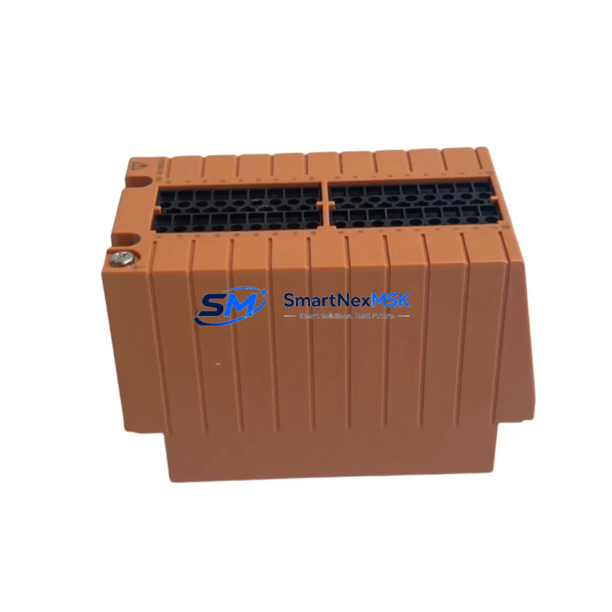
Designed to mount directly onto standard DIN rail within the STB Series marshalling cabinet, the STB4D-10 S2 supports dual-channel SIL 2 digital input and output configurations. Its screw-terminal wiring interface is fully compatible with existing field cable schedules, eliminating the need to re-terminate field wiring during a module swap. The module’s backplane connector aligns with the STB Series bus coupler, ensuring that no mechanical adapter or custom bracket is required during installation. Engineers performing a like-for-like replacement of a failed or end-of-life STB4D-10 unit will find the S2 revision maintains full backward compatibility with the original module’s I/O addressing scheme and diagnostic behavior.
Upgrade Compatibility Table
| Parameter | STB4D-10 S2 (This Unit) | Legacy STB4D-10 (Original) | Retrofit Notes |
|---|---|---|---|
| Channel Configuration | Dual-channel DI/DO | Dual-channel DI/DO | Direct drop-in; no logic change required |
| Safety Integrity Level | SIL 2 certified | SIL 2 certified | Certification maintained post-swap |
| Backplane Interface | STB Series bus coupler | STB Series bus coupler | No adapter required |
| Wiring Terminal Type | Screw terminal, 0.2–2.5 mm² | Screw terminal, 0.2–2.5 mm² | Existing field cables reusable |
| Power Supply Compatibility | 24 VDC via bus coupler | 24 VDC via bus coupler | Verify bus coupler load budget before swap |
| Module Address Assignment | Configured via ProSafe-RS SCS | Configured via ProSafe-RS SCS | Retain original slot address; no re-download needed if slot unchanged |
| Communication Protocol | Vnet/IP (ProSafe-RS) | Vnet/IP (ProSafe-RS) | No protocol migration required |
| HMI Integration | CENTUM VP / Exaopc compatible | CENTUM VP / Exaopc compatible | Existing HMI faceplates remain valid |
| Commissioning Requirement | Loop test + SCS online download | Loop test + SCS online download | Online change supported if SCS version ≥ R4.01 |
| Warranty | 12 months from shipment | OEM warranty expired | Full 12-Month Warranty included with every unit |
Retrofit Planning for Existing Automation Systems
A successful STB4D-10 S2 retrofit begins well before the module arrives on site. The first step is a thorough review of the existing STB Series rack layout and bus coupler load calculation. Each STB bus coupler — such as the STB-BUS-COUPLER or its successor variants — has a defined maximum current budget for the terminal blocks it powers. Adding or replacing modules without verifying this budget risks nuisance trips or bus communication faults. Confirm that the 24 VDC supply feeding the safety cabinet, typically sourced from a dedicated Yokogawa PW301 or PW302 power supply module, has sufficient headroom to support the S2 revision’s inrush current during power-up.
Next, review the field terminal wiring schedule against the STB4D-10 S2 terminal assignment diagram. In most STB Series installations, field cables are landed on separate marshalling terminals before being jumpered to the module’s screw terminals. This arrangement means the STB4D-10 S2 can be swapped without disturbing field wiring, provided the marshalling terminal strip — often a Yokogawa TB series or equivalent Phoenix Contact terminal block — is left intact. Photograph and document all jumper positions before removal.
For facilities running ProSafe-RS Safety Control Stations (SCS), the module address is defined in the SCS hardware configuration and compiled into the safety application. If the STB4D-10 S2 is installed in the same physical slot as the removed module, the SCS will recognize it at the same I/O address without requiring a full application re-download. However, if the slot position changes — for example, due to rack reconfiguration or the addition of an STB-EXT extension rack — the SCS hardware configuration must be updated and a controlled online change or offline download must be performed. Coordinate this with the site’s functional safety engineer and ensure a pre-change backup of the SCS application, including all cause-and-effect matrices and interlock logic, is stored securely before proceeding.
HMI screens built in CENTUM VP or accessed via Exaopc OPC server will continue to display correct I/O status after the swap, as the tag database references the I/O address rather than the physical module part number. Verify that any diagnostic alarms associated with the old module — such as channel fault or module removed alerts — are cleared and reset in the CENTUM VP alarm management system after the new STB4D-10 S2 is confirmed online. If the facility uses a Yokogawa FAST/TOOLS SCADA layer above CENTUM VP, confirm that the relevant tag aliases are refreshed in the FAST/TOOLS tag browser following commissioning.
Sites migrating from older Yokogawa FA-M3 or STARDOM FCN/FCJ controller platforms to ProSafe-RS will find the STB4D-10 S2 a natural endpoint for I/O consolidation. In these migration projects, the STB Series terminal blocks serve as the field interface layer while the ProSafe-RS SCS takes over safety logic execution. A Yokogawa ALF111 or ALR111 analog input module may be installed in adjacent slots to handle 4–20 mA transmitter signals, while the STB4D-10 S2 manages discrete safety interlock inputs and outputs. Programming cables such as the Yokogawa KS1-USB or equivalent are used during initial SCS configuration and should be retained on site for future maintenance downloads.
Downtime Control During System Migration
Minimizing unplanned downtime is the primary concern for any safety system retrofit. The STB4D-10 S2 supports hot-swap replacement in ProSafe-RS systems where the SCS is configured for online module replacement — a feature available from SCS firmware R4.01 onward. Before initiating a hot-swap, place the affected I/O channel in bypass mode within the SCS safety application to prevent spurious trips during the physical module exchange. Document the bypass activation in the site’s management of change (MOC) log and obtain the required authorization from the safety officer.
Once the bypass is active, de-energize the field circuit at the marshalling terminal, remove the failed or end-of-life STB4D-10 module, and insert the STB4D-10 S2 into the same slot. The bus coupler will detect the new module within seconds and the SCS will perform an automatic self-test sequence. Monitor the SCS diagnostic display — accessible via the ProSafe-RS Engineering Environment or the CENTUM VP system status viewer — for module OK confirmation before removing the bypass. Perform a full loop test on each channel: apply a test signal at the field terminal, verify the SCS input status changes correctly, and confirm the output relay or solid-state output responds as expected.
For sites where online replacement is not available — typically older SCS revisions or systems operating in a degraded state — a planned shutdown window must be scheduled. In this scenario, prepare a detailed step-by-step switching procedure, coordinate with operations to place the affected process unit in a safe state, and ensure a spare STB4D-10 S2 is physically on site before the window begins. Pre-staging the replacement module, verifying its firmware revision against the SCS hardware configuration, and confirming the 12-month warranty documentation is in order will reduce the risk of delays during the maintenance window.
Retrofit Support FAQ
Q1: Is the STB4D-10 S2 a direct replacement for the original STB4D-10?
Yes. The S2 revision is a form-fit-function replacement for the original STB4D-10. It uses the same backplane connector, the same screw-terminal wiring layout, and the same I/O addressing scheme within the ProSafe-RS SCS. No hardware adapter, wiring modification, or SCS application change is required when replacing like-for-like in the same rack slot.
Q2: What pre-shipment testing is performed on each unit?
Every STB4D-10 S2 unit undergoes functional verification testing prior to shipment, including power-on self-test, channel continuity check, and communication handshake verification with a reference STB bus coupler. A test report is available upon request. Each unit ships with a 12-month warranty covering manufacturing defects and functional failures under normal operating conditions.
Q3: Can the STB4D-10 S2 be used in a mixed STB Series rack alongside other module types?
Yes. The STB Series architecture supports mixed module configurations within the same rack. The STB4D-10 S2 can be installed alongside analog input modules, analog output modules, digital output modules, and communication interface modules within the same STB bus coupler segment, subject to the bus coupler’s total current budget. Refer to the STB Series system configuration guide for slot assignment rules and current load calculations.
Q4: What is the warranty coverage and what does it include?
All units supplied by SMARTNEXMSK carry a 12-month warranty from the date of shipment. The warranty covers functional failures attributable to manufacturing defects, including channel faults, communication errors, and power supply failures within the module. It does not cover damage resulting from incorrect installation, overvoltage, or operation outside the specified environmental range. Warranty claims are processed within 5 business days of receipt of the returned unit, with replacement or repair at SMARTNEXMSK’s discretion.
© 2026 SMARTNEXMSK. All rights reserved.
Original Source: https://smartnexmsk.com
Contact: sales@smartnexmsk.com | +86 18259474341


