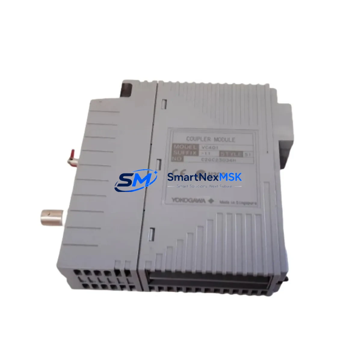
Yokogawa VC401-11 S1 Retrofit-Ready V Net Coupler for CENTUM VP Control Systems
The Yokogawa VC401-11 S1 is a V Net Coupler Module designed for integration within the CENTUM VP Distributed Control System (DCS) platform. As legacy CENTUM CS 3000 and earlier CENTUM VP installations reach end-of-service milestones, the VC401-11 S1 has become a critical retrofit component for engineers tasked with modernizing control architectures without full system replacement. This module enables seamless V Net communication coupling between field control stations, engineering workstations, and operator interface terminals, preserving existing network topology while extending system service life.
At SMARTNEXMSK, every VC401-11 S1 unit is sourced from verified supply channels, subjected to functional bench testing prior to dispatch, and covered by a 12-month warranty. Our inventory supports urgent replacement scenarios, planned turnarounds, and long-cycle procurement programs for facilities operating CENTUM VP-based control infrastructure.
Upgrade Compatibility Table
| Parameter | Details |
|---|---|
| Compatible Platform | Yokogawa CENTUM VP, CENTUM CS 3000 (with engineering review) |
| Module Function | V Net Coupler — couples V Net segments within FCS/BCV cabinets |
| Communication Protocol | V Net (Yokogawa proprietary real-time control bus) |
| Backplane Interface | Standard CENTUM VP node unit backplane slot |
| Installation Requirement | Fits standard Yokogawa node unit (NU) rack; confirm slot addressing before installation |
| Power Supply Compatibility | Powered via backplane; verify PW481 or PW482 power supply capacity before hot-swap |
| Replacement Candidates | VC401-10, VC401-11 (earlier suffix revisions) |
| Commissioning Note | Module address must be confirmed in CENTUM VP Builder before power-on; HMI tag re-mapping may be required |
| Outgoing Test | Functional test performed prior to shipment |
| Warranty | 12 months from date of delivery |
Retrofit Planning for Existing Automation Systems
Replacing a V Net Coupler in an operating CENTUM VP system requires careful pre-work to avoid unplanned process interruptions. Before removing the existing VC401-11 S1 or its predecessor, engineers should document the current V Net segment configuration using CENTUM VP Builder and export a full system backup. The node unit rack — typically housed alongside the CP451 or CP461 Field Control Station processor — must be inspected for available slot positions and backplane continuity.
Power budget verification is essential. The PW481 or PW482 power supply modules feeding the node unit must have sufficient headroom to support the replacement coupler without triggering undervoltage alarms on adjacent I/O modules such as the AAI141 analog input module or ADV151 digital input module. Terminal wiring on the V Net coaxial or fiber connections should be labeled and photographed before disconnection.
For facilities migrating from CENTUM CS 3000 to CENTUM VP, the VC401-11 S1 may serve as a bridging component during phased migration, allowing legacy FCS0403 field control stations to remain online while new CENTUM VP nodes are commissioned in parallel. Communication module compatibility — particularly for ESB10D Ethernet communication modules or ER Bus interface cards — should be validated against the target CENTUM VP release version.
I/O expansion during retrofit often involves adding AAT141 analog output modules or ADV551 digital output modules to existing node racks. Each new module requires address assignment in CENTUM VP Builder and corresponding tag creation in the HMI project. Operators should be briefed on temporary HMI screen changes during the cutover window to avoid misinterpretation of alarm states.
Programming cable connectivity — typically via the ACM12 or a standard RS-232/USB engineering port — should be confirmed before the maintenance window begins. Having a pre-tested spare VC401-11 S1 on the bench, with its module address pre-configured, reduces live installation time significantly and supports a controlled, low-risk swap procedure.
Downtime Control During System Migration
Minimizing control system downtime during a V Net Coupler replacement begins with a structured pre-outage checklist. All process variables routed through the affected V Net segment should be identified, and operators should place relevant control loops in manual mode before the coupler is de-energized. The existing VC401-11 S1 should be removed only after confirming that the replacement unit has been pre-addressed and bench-verified.
Where process continuity is critical, a temporary bypass strategy using redundant V Net paths — if the system architecture supports dual-coupler configurations — can maintain partial communication during the swap. CENTUM VP’s built-in diagnostic tools, accessible via the CENTUM VP HIS (Human Interface Station), allow real-time monitoring of V Net segment health and can confirm successful coupler re-integration before control loops are returned to automatic mode.
Post-installation, a structured loop check sequence should verify that all I/O signals previously routed through the replaced coupler are reading correctly at the HIS operator station. Any discrepancies in analog scaling or digital state should be resolved before the maintenance window closes. Full system backup should be re-exported from CENTUM VP Builder after the replacement is confirmed stable, and the event log should be reviewed to confirm no latent alarms were masked during the outage period.
Retrofit Support FAQ
Q1: Is the VC401-11 S1 a direct drop-in replacement for the VC401-10?
The VC401-11 S1 is functionally compatible with VC401-10 applications in most CENTUM VP configurations. However, suffix revision differences may affect firmware behavior in specific CENTUM VP software releases. We recommend confirming the target system’s CENTUM VP version with your Yokogawa engineering documentation before installation. Our technical team can assist with compatibility verification prior to order.
Q2: What pre-installation checks are required for backplane and wiring compatibility?
Verify that the target node unit rack slot is physically clear and that the backplane connector shows no corrosion or mechanical damage. Confirm V Net coaxial or fiber termination type matches the VC401-11 S1 interface. Check that the PW481/PW482 power supply load budget accommodates the replacement module. Document all terminal assignments before disconnecting the existing coupler.
Q3: Has the unit been tested before shipment, and what does the 12-month warranty cover?
Yes. Every VC401-11 S1 dispatched by SMARTNEXMSK undergoes functional bench testing to verify communication coupling performance and backplane interface integrity. The 12-month warranty covers manufacturing defects and functional failures under normal operating conditions. It does not cover damage resulting from incorrect installation, overvoltage, or environmental exposure beyond the module’s rated specifications.
Q4: Can this module be used in a CENTUM CS 3000 system?
The VC401-11 S1 is primarily specified for CENTUM VP. Use in CENTUM CS 3000 environments requires engineering review, as V Net protocol implementations differ between platforms. We recommend consulting your system’s hardware compatibility matrix or contacting our sales team for a pre-sale technical assessment before committing to this part for a CS 3000 application.
© 2026 SMARTNEXMSK. All rights reserved.
Original Source: https://smartnexmsk.com
Contact: sales@smartnexmsk.com | +86 18259474341


