YOKOGAWA VI451-10 S2 Retrofit-Ready Interface for CENTUM VP Control Systems
The YOKOGAWA VI451-10 S2 is a communication interface module engineered for seamless integration into CENTUM VP distributed control system architectures. As legacy CENTUM CS 3000 and earlier CENTUM VP field stations approach end-of-life, plant engineers and system integrators increasingly rely on the VI451-10 S2 as a verified, drop-in compatible replacement that preserves existing wiring infrastructure, backplane slot assignments, and communication link configurations. Whether you are executing a phased control cabinet upgrade, migrating from an obsolete communication card, or restoring a critical production line after an unplanned failure, the VI451-10 S2 delivers the compatibility and reliability your operation demands.
Sourced directly from authorized distribution channels and subject to full functional testing prior to shipment, every VI451-10 S2 unit leaves our facility verified against YOKOGAWA’s original factory specifications. We maintain ready stock to support emergency procurement scenarios where lead time from the OEM is not acceptable. All units are covered by a 12-month warranty against manufacturing defects and functional failure under normal operating conditions.
Upgrade Compatibility Table
| Parameter | Detail |
|---|---|
| Compatible Platform | YOKOGAWA CENTUM VP, CENTUM CS 3000 (with engineering review) |
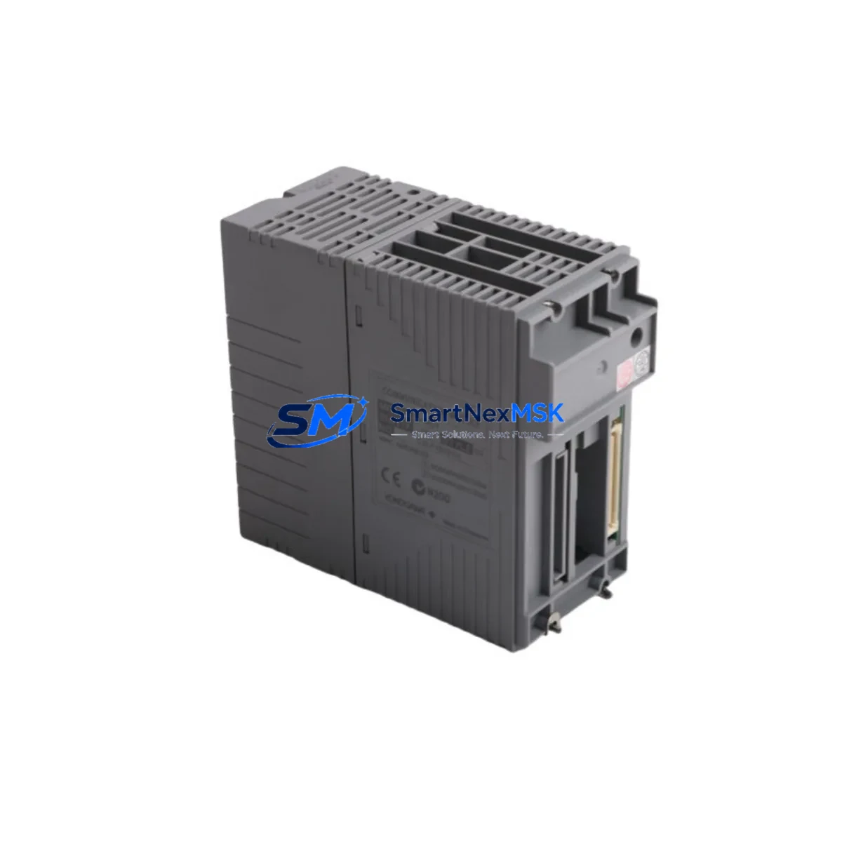
| Module Type | Communication Interface Module |
| SKU / Part Number | VI451-10 S2 |
| Backplane Interface | Standard CENTUM VP field control station (FCS) backplane slot |
| Communication Protocol | Vnet/IP (YOKOGAWA proprietary high-speed control bus) |
| Replacement Compatibility | Direct replacement for VI451-10 (earlier suffix variants — verify suffix revision with engineering) |
| Power Supply Requirement | Supplied via FCS backplane; verify total FCS power budget before installation |
| Installation Requirement | Hot-swap capable in supported FCS configurations; cold-swap recommended for first-time retrofit |
| Address / Node Configuration | Module address set via hardware DIP switch or engineering tool; verify against existing FCS node map |
| HMI / SCADA Compatibility | Compatible with CENTUM VP HIS (Human Interface Station) and third-party OPC DA/UA clients |
| Commissioning Requirement | Download and verify FCS project after module swap; confirm communication link status in CENTUM VP Builder |
| Warranty | 12 months from date of shipment — covers manufacturing defects and functional failure |
Retrofit Planning for Existing Automation Systems
A successful VI451-10 S2 retrofit begins well before the module arrives on site. During the pre-engineering phase, your team should audit the existing field control station to confirm available backplane slots, total power consumption across installed I/O modules, and the current Vnet/IP node address map. In a typical CENTUM VP FCS cabinet, the communication interface module occupies a dedicated slot adjacent to the processor card — commonly the CP451 or CP461 field control unit — and shares the backplane bus with analog input modules such as the AAI141 or AAI543, digital output modules including the ADO141, and pulse input cards. Confirming that the replacement VI451-10 S2 carries the correct suffix revision (S2 in this case) is critical, as earlier suffix variants may differ in firmware compatibility with the installed CP unit.
Power budget verification is a mandatory step that is frequently overlooked during emergency replacements. The FCS power supply module — typically a PW481 or PW482 unit — must have sufficient headroom to support the VI451-10 S2 alongside all co-installed I/O and communication cards. If the existing power supply is already operating near capacity due to previously added I/O expansion modules, a parallel power supply or load redistribution may be required before the retrofit can proceed safely.
Terminal wiring on the VI451-10 S2 follows YOKOGAWA’s standard field terminal block layout. In most CENTUM VP installations, the communication interface module does not carry field wiring directly — signal termination is handled at the I/O module level — but the Vnet/IP fiber or copper link must be re-terminated and verified for signal integrity after the swap. If the plant is migrating from an older CENTUM CS 3000 architecture that used the legacy ESB bus rather than Vnet/IP, a protocol migration plan must be developed in conjunction with YOKOGAWA engineering or a certified system integrator, as the VI451-10 S2 is native to the Vnet/IP environment.
For plants running YOKOGAWA’s CENTUM VP R6 or later, the engineering environment (CENTUM VP Builder) supports online module replacement with minimal disruption to running control loops, provided the FCS is configured for redundant communication. In non-redundant configurations, a planned maintenance window is required. During this window, the existing FCS project should be backed up, the module swapped, and a full project download executed to re-establish communication link parameters. HMI faceplates on the HIS (Human Interface Station) should be verified post-commissioning to confirm all tag references resolve correctly and no communication alarms persist.
If the retrofit scope extends beyond a single communication interface module — for example, when simultaneously upgrading the FCS processor from a CP451 to a CP461, adding ALR111 alarm management modules, or expanding I/O capacity with additional AAI841 analog input cards — a staged migration plan is strongly recommended. Completing and verifying the VI451-10 S2 swap as an isolated step before proceeding to processor or I/O changes reduces diagnostic complexity and shortens overall commissioning time.
Downtime Control During System Migration
Minimizing unplanned downtime is the primary operational concern during any communication interface module replacement in a live production environment. The VI451-10 S2 supports YOKOGAWA’s standard FCS redundancy architecture, which allows the standby communication path to maintain control continuity while the primary module is replaced. Before initiating the swap, confirm that the redundancy switchover has been tested and that the standby FCS or redundant communication link is fully operational — do not assume redundancy is active simply because it was configured at commissioning.
Prior to physical module removal, export and archive the current FCS project from CENTUM VP Builder, including all function block definitions, loop tuning parameters, interlock logic, and communication link assignments. This archive serves as the recovery baseline if the post-swap download encounters errors. In plants where the FCS controls safety-critical loops, coordinate with the process safety team to confirm that the Safety Instrumented System (SIS) — if present, often a ProSafe-RS unit in YOKOGAWA installations — remains in a safe state throughout the migration window.
After installing the VI451-10 S2, perform a visual inspection of the backplane connector seating before powering the FCS. Execute the project download, monitor the communication link status indicators on the module front panel, and verify that all Vnet/IP node addresses are recognized by the FCS processor. Confirm that the HIS displays live process values for all tags associated with the upgraded FCS before releasing the system back to operations. Document the as-found and as-left configuration, including module serial number, firmware version, and any DIP switch settings, as part of the plant’s maintenance record.
Retrofit Support FAQ
Q1: Is the VI451-10 S2 a direct drop-in replacement for earlier VI451-10 suffix variants?
The VI451-10 S2 is generally compatible with the same backplane slot and Vnet/IP communication architecture as earlier suffix variants. However, suffix revisions in YOKOGAWA modules can reflect firmware or hardware changes that affect compatibility with specific CP unit versions. We recommend confirming the installed CP unit model and firmware revision with your engineering team or contacting us with your FCS configuration details before ordering.
Q2: What commissioning steps are required after installing the VI451-10 S2?
After physical installation, a full FCS project download from CENTUM VP Builder is required to re-establish communication link parameters and module address assignments. Verify Vnet/IP link status on the module front panel LEDs, confirm all I/O tags are communicating correctly on the HIS, and clear any residual communication alarms. In redundant FCS configurations, test the redundancy switchover after commissioning to confirm both communication paths are operational.
Q3: Can the VI451-10 S2 be used in a CENTUM CS 3000 system?
The VI451-10 S2 is designed for the CENTUM VP platform and its Vnet/IP communication architecture. CENTUM CS 3000 systems use a different communication bus (ESB bus). Direct installation into a CS 3000 FCS without platform migration engineering is not supported. If you are migrating from CS 3000 to CENTUM VP, the VI451-10 S2 is the correct module for the target platform — contact us to discuss your migration scope.
Q4: What does the 12-month warranty cover, and what is the return process?
All VI451-10 S2 units are covered by a 12-month warranty from the date of shipment. The warranty covers manufacturing defects and functional failure under normal operating conditions. Units that fail within the warranty period should be returned with a description of the failure mode and the operating environment. We will repair or replace the unit at no charge. Warranty does not cover damage resulting from incorrect installation, overvoltage, or physical impact.
© 2026 SMARTNEXMSK. All rights reserved.
Original Source: https://smartnexmsk.com
Contact: sales@smartnexmsk.com | +86 18259474341


