
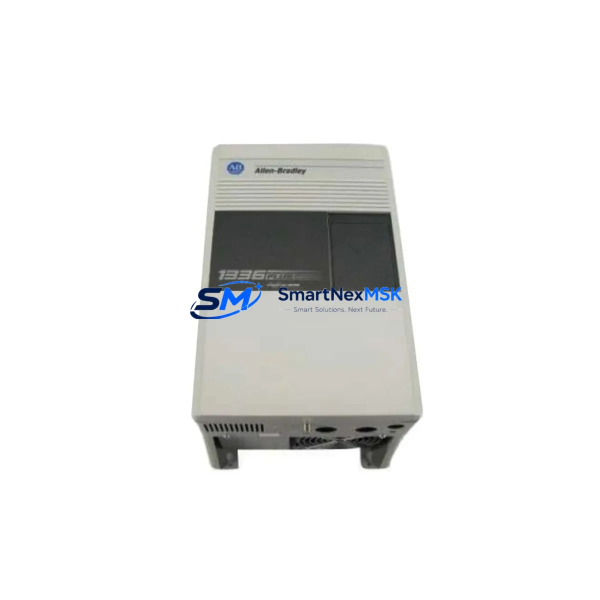
Allen-Bradley 1336F-BRF75-AE-DE Retrofit-Ready VFD for 1336 PLUS II Control Systems
The Allen-Bradley 1336F-BRF75-AE-DE is a 75HP (55kW) AC Variable Frequency Drive from the 1336 PLUS II series, designed for demanding industrial motor control applications. As the 1336 PLUS II platform approaches end-of-life and spare parts become increasingly scarce, this unit serves as a verified retrofit solution for facilities operating legacy control systems built around Rockwell Automation’s 1336 architecture. Whether you are replacing a failed drive in a continuous process line, upgrading a control cabinet, or executing a planned migration to a more supportable platform, the 1336F-BRF75-AE-DE provides the electrical and mechanical compatibility required for a smooth transition with minimal engineering rework.
Upgrade Compatibility Table
| Parameter | Details |
|---|---|
| SKU / Part Number | 1336F-BRF75-AE-DE |
| Series | Allen-Bradley 1336 PLUS II |
| Power Rating | 75HP / 55kW |
| Input Voltage | 380–480V AC, 3-Phase |
| Output Frequency | 0–400 Hz |
| Enclosure | IP20 / NEMA Type 1 (chassis mount) |
| Communication Interface | DH-485 / Remote I/O (RIO) via 1336-GM6 or 1336-GM1 option card |
| Replaces / Compatible With | 1336F-BRF75-AE, 1336F-BRF75-AA-DE, 1336 PLUS (first generation) with wiring adaptation |
| Mounting | Standard 1336 PLUS II chassis footprint; backplane-independent standalone drive |
| Programming Tool | DriveExplorer, DriveExecutive, 1336-MOD-L2 HIM keypad |
| Retrofit Complexity | Low-to-medium — terminal mapping and parameter migration required |
| Debugging Focus | Accel/decel ramp, current limit, fault log review, encoder feedback if applicable |
| Warranty | 12-Month Warranty from date of shipment |
Retrofit Planning for Existing Automation Systems
Successful integration of the 1336F-BRF75-AE-DE into an existing control system begins with a thorough audit of the current installation. Before removing the failed or obsolete drive, engineers should document all terminal wiring on the existing unit — particularly the control terminal block assignments for analog speed reference (TB3), digital inputs for Run/Stop/Fault Reset, and any hardwired safety interlock circuits. The 1336 PLUS II uses a standardized terminal layout, but field modifications made over years of operation are common and must be captured before work begins.
Power supply capacity is a critical checkpoint. The 1336F-BRF75-AE-DE draws significant inrush current at startup; verify that the upstream MCC section, circuit breaker, and line reactor — such as a 1321-3R75-B line reactor — are rated for the 75HP load. If the existing installation used a 1336-MOD-FA2 dynamic braking option, confirm whether the braking resistor assembly and the 1336-BRB75 brake unit remain compatible with the replacement drive’s braking chopper interface.
For systems communicating over Remote I/O (RIO), the drive must be configured with the correct node address, baud rate (57.6K or 115.2K), and rack/group/slot assignments to match the existing PLC-5 or SLC 500 scanner configuration. If the host controller is a ControlLogix or CompactLogix platform using a 1756-DHRIO or 1747-SN scanner, verify that the RIO adapter parameters in the drive match the scanner’s I/O map exactly. Mismatched node addresses are the most common cause of communication faults during commissioning.
Where the legacy system used a 1336-GM6 DeviceNet option card or a 1336-GM1 DH-485 adapter, these option cards are typically retained and reinstalled in the replacement drive, provided the card firmware is compatible with the new drive’s base firmware revision. Always confirm the option card catalog number and revision before reuse. In some cases, a 20-COMM-D DeviceNet adapter from the PowerFlex family may be considered as part of a broader protocol migration strategy.
HMI screens built on PanelView 550, PanelView 900, or PanelView Plus terminals that display drive status, speed feedback, and fault codes typically reference parameter numbers directly. After replacing the drive, verify that the parameter numbers for Output Frequency (P003), Output Current (P004), DC Bus Voltage (P005), and Fault Code (P007) remain consistent with the HMI tag database. If the HMI application was developed in RSView32 or FactoryTalk View ME, a parameter cross-reference check is recommended before returning the system to production.
I/O expansion requirements should also be reviewed. If the control system uses a 1746-NI4 analog input module or a 1746-NO4I analog output module in an SLC 500 rack to provide speed reference and feedback signals to the drive, confirm that the signal scaling (0–10V or 4–20mA) matches the drive’s analog input configuration. Incorrect scaling will result in incorrect speed commands and potential process upsets.
Downtime Control During System Migration
Minimizing unplanned downtime during a drive replacement requires preparation that begins well before the maintenance window. The recommended approach is to pre-configure the replacement 1336F-BRF75-AE-DE on the bench using DriveExplorer software and a 1784-U2DHP USB-to-DH+ adapter, uploading the parameter file from the failed drive if it can still communicate, or rebuilding the parameter set from the last known-good backup stored in the plant’s document management system.
During the physical swap, label all control wiring before disconnection. Use the drive’s built-in fault log (accessible via the 1336-MOD-L2 HIM or DriveExplorer) to capture the last five fault codes from the outgoing unit — this data often reveals whether the failure was caused by an upstream power quality issue, motor insulation degradation, or a control logic fault that must be addressed before the replacement drive is energized.
After installation, perform a no-load test by disconnecting the motor leads and running the drive through its full speed range to verify control signal integrity, analog input scaling, and digital I/O response. Reconnect the motor and perform a low-speed bump test before returning to full production speed. This staged commissioning approach typically reduces total downtime to under four hours for a straightforward 1336 PLUS II replacement, even in complex multi-drive control cabinet configurations.
For facilities with zero-tolerance downtime requirements, a pre-staged spare drive — fully parameterized and tested — should be maintained in inventory. SMARTNEXMSK maintains stock of the 1336F-BRF75-AE-DE and related 1336 PLUS II components to support emergency dispatch requirements.
Retrofit Support FAQ
Q1: Is the 1336F-BRF75-AE-DE a direct drop-in replacement for the 1336F-BRF75-AE?
Yes, the -DE suffix denotes the addition of the DeviceNet communication option. The base drive hardware, terminal layout, mounting dimensions, and power ratings are identical to the 1336F-BRF75-AE. If your existing installation does not use DeviceNet, the -DE option card can be left unpopulated or ignored without affecting drive operation.
Q2: Can this drive be used to replace a first-generation 1336 PLUS (non-PLUS II) unit?
Yes, with adaptation. The 1336 PLUS II shares the same power section architecture as the original 1336 PLUS but uses a different control board and parameter structure. Terminal wiring is largely compatible, but parameter numbers differ. A full parameter re-entry is required, and the HMI tag database must be updated to reflect the PLUS II parameter map. Consult the 1336 PLUS II Programming Manual (publication 1336PLUS-6.2) for the complete parameter cross-reference.
Q3: What pre-shipment testing is performed on this unit?
Each 1336F-BRF75-AE-DE supplied by SMARTNEXMSK undergoes a full power-on functional test, including DC bus charge verification, output voltage balance across all three phases, and digital I/O response check. A test report is available upon request. All units are covered by a 12-month warranty from the date of shipment, covering manufacturing defects and functional failures under normal operating conditions.
Q4: What is the lead time, and do you hold stock?
SMARTNEXMSK maintains ready stock of the 1336F-BRF75-AE-DE to support urgent replacement requirements. Standard orders ship within 1–3 business days. For large-quantity orders or project-based procurement, contact our sales team to confirm availability and arrange expedited logistics.
© 2026 SMARTNEXMSK. All rights reserved.
Original Source: https://smartnexmsk.com
Contact: [email protected] | +86 18259474341



