
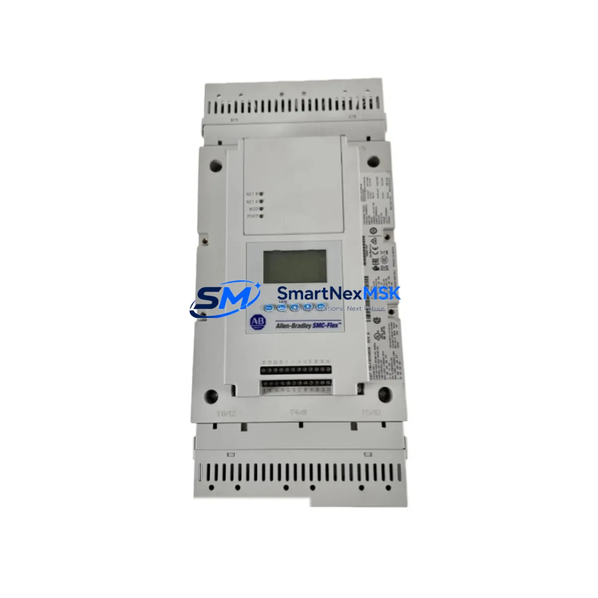
Allen-Bradley 150-F201NBDB Maintenance-Ready Spare for SMC-Flex Automation
The Allen-Bradley 150-F201NBDB is a 201A full-voltage soft starter from the SMC-Flex series, engineered for demanding industrial motor control applications. As a maintenance-ready original spare, this unit supports rapid field replacement in manufacturing lines, process plants, pump stations, compressor rooms, and HVAC systems where unplanned downtime carries significant operational cost. With DeviceNet communication, integrated bypass contactor, and dynamic braking output, the 150-F201NBDB delivers the control flexibility that maintenance and procurement engineers require when managing aging automation infrastructure.
Sourced as an original Allen-Bradley component, each unit undergoes pre-shipment functional verification to confirm communication integrity, parameter retention, and output response. A 12-month warranty covers all units, providing procurement teams with the confidence needed for long-term spare parts planning and MRO inventory commitments.
Spare Maintenance Table
| Parameter | Specification |
|---|---|
| SKU / Part Number | 150-F201NBDB |
| Brand | Allen-Bradley (Rockwell Automation) |
| Series | SMC-Flex |
| Product Type | Soft Starter |
| Current Rating | 201A |
| Supply Voltage | 200–600V AC, 3-Phase |
| Control Voltage | 100–240V AC |
| Communication | DeviceNet (integrated) |
| Bypass | Integrated Bypass Contactor |
| Braking | Dynamic Braking Output |
| Enclosure | Open / Panel Mount |
| Origin | United States |
| Compatibility | SMC-Flex Series; replaces 150-F201NBD, 150-F201NB |
| Application Environment | Industrial: pumps, fans, compressors, conveyors, HVAC |
| Maintenance Recommendation | Inspect bypass contacts, DeviceNet node address, and parameter backup before installation |
| Warranty | 12 Months from shipment date |
| Condition | Original / New Surplus / Tested |
| Lead Time | In stock — ships within 1–3 business days |
Maintenance Planning for Continuous Operation
When replacing the 150-F201NBDB in a live control cabinet, a disciplined maintenance approach prevents secondary failures and reduces total downtime. Maintenance engineers should treat this replacement as an opportunity to audit the surrounding electrical circuit and associated components.
Begin with the input power section: verify the upstream circuit breaker or fused disconnect is rated for 201A motor branch circuits. Check the line-side power cables for insulation integrity and terminal torque — loose connections at this current rating generate heat that accelerates insulation degradation. Inspect the load-side motor cables and confirm cable shielding is intact, particularly in environments with high-frequency VFD interference nearby.
The integrated bypass contactor within the 150-F201NBDB eliminates the need for an external bypass, but the control circuit wiring to terminals 1–14 should be verified against the original wiring diagram. If the installation previously used a 150-SMC-NEMA-style external bypass module, confirm it has been properly decommissioned to avoid control conflicts.
For DeviceNet-connected installations, verify the DeviceNet network drop cable and confirm the node address matches the original configuration. A 1769-SDN DeviceNet Scanner or equivalent module in the ControlLogix or CompactLogix rack should be checked for node table integrity after the replacement. If the system uses a 1756-DNB DeviceNet Bridge, confirm the EDS file version is compatible with the 150-F201NBDB firmware.
Inspect the 24VDC control power supply feeding the DeviceNet segment — voltage sag below 21.6V can cause intermittent communication faults that are often misdiagnosed as starter failures. A 1606-XLP power supply or equivalent should be load-tested if the segment serves multiple nodes.
Check the motor thermistor or PTC input wiring if thermal protection is enabled in the starter parameters. Verify the overload relay settings are correctly restored after parameter upload — the SMC-Flex stores motor FLA, service factor, and trip class settings that must match the driven motor nameplate. If the motor has been rewound or replaced, update these parameters accordingly.
For systems with dynamic braking, inspect the braking resistor bank and its thermal cutout. A failed braking resistor will not prevent the starter from operating but will disable controlled deceleration, increasing mechanical wear on couplings and driven equipment. Finally, review the I/O status indicators on the starter faceplate and confirm all fault codes are cleared before returning the system to automatic control.
Site Replacement Workflow
Step 1 — Isolation: De-energize the motor branch circuit at the upstream disconnect. Apply LOTO (Lockout/Tagout) per site safety procedures. Verify absence of voltage at the starter input terminals using a calibrated meter.
Step 2 — Parameter Backup: If the existing 150-F201NBDB is still partially functional, connect a laptop with RSLinx Classic or Studio 5000 Logix Designer and upload the parameter file. Save the .RSS or .ACD file with the equipment tag and date. If the unit is non-responsive, retrieve parameters from the PLC program or the site maintenance log.
Step 3 — Mechanical Removal: Disconnect all power and control wiring, labeling each terminal. Remove the unit from the panel using the mounting rail or bolt pattern. Note the physical orientation — the 150-F201NBDB is designed for vertical mounting with airflow clearance above and below.
Step 4 — Installation: Mount the replacement unit. Reconnect power wiring to specified torque values (refer to publication 150-UM009). Reconnect control wiring and DeviceNet drop cable. Set the node address rotary switches to match the original configuration.
Step 5 — Parameter Restore: Download the saved parameter file to the replacement unit. Verify motor FLA, trip class, ramp times, and communication settings. Confirm the bypass contactor operates correctly during a no-load test start.
Step 6 — Commissioning: Re-energize the circuit. Perform a controlled test start under reduced load if possible. Monitor DeviceNet status on the scanner module. Confirm all I/O signals are responding correctly before returning to full production.
This workflow minimizes mean time to repair (MTTR) and ensures the replacement 150-F201NBDB is fully integrated into the existing control architecture without introducing new fault conditions.
Spare Parts Support FAQ
Q1: Is the 150-F201NBDB a direct replacement for the 150-F201NBD?
Yes. The 150-F201NBDB adds the dynamic braking output (DB suffix) to the base 150-F201NBD configuration. It is mechanically and electrically compatible with the same panel cutout and wiring scheme. If dynamic braking is not used in your application, the DB terminals can be left unconnected without affecting starter operation.
Q2: How is the unit tested before shipment?
Each 150-F201NBDB is inspected for physical condition, firmware version, and communication response prior to packaging. Units are powered and checked for fault-free startup, parameter accessibility, and DeviceNet node response. A test report is available upon request for critical infrastructure applications.
Q3: What is the recommended spare parts holding strategy for SMC-Flex installations?
For facilities operating multiple SMC-Flex starters, a minimum of one spare unit per current rating tier is recommended. The 150-F201NBDB covers the 201A tier. Facilities with high motor density should also maintain spares for the 150-F135NBD (135A) and 150-F251NBD (251A) tiers to cover adjacent ratings. Storing a spare alongside a parameter backup file reduces replacement time to under two hours in most installations.
Q4: What does the 12-month warranty cover?
The 12-month warranty covers manufacturing defects, component failures under normal operating conditions, and communication interface faults. It does not cover damage resulting from incorrect installation, overvoltage events, or failure to follow the torque and clearance specifications in publication 150-UM009. Warranty claims are processed within 5 business days of receipt of the returned unit.
© 2026 SMARTNEXMSK. All rights reserved.
Original Source: https://smartnexmsk.com
Contact: [email protected] | +86 18259474341



