
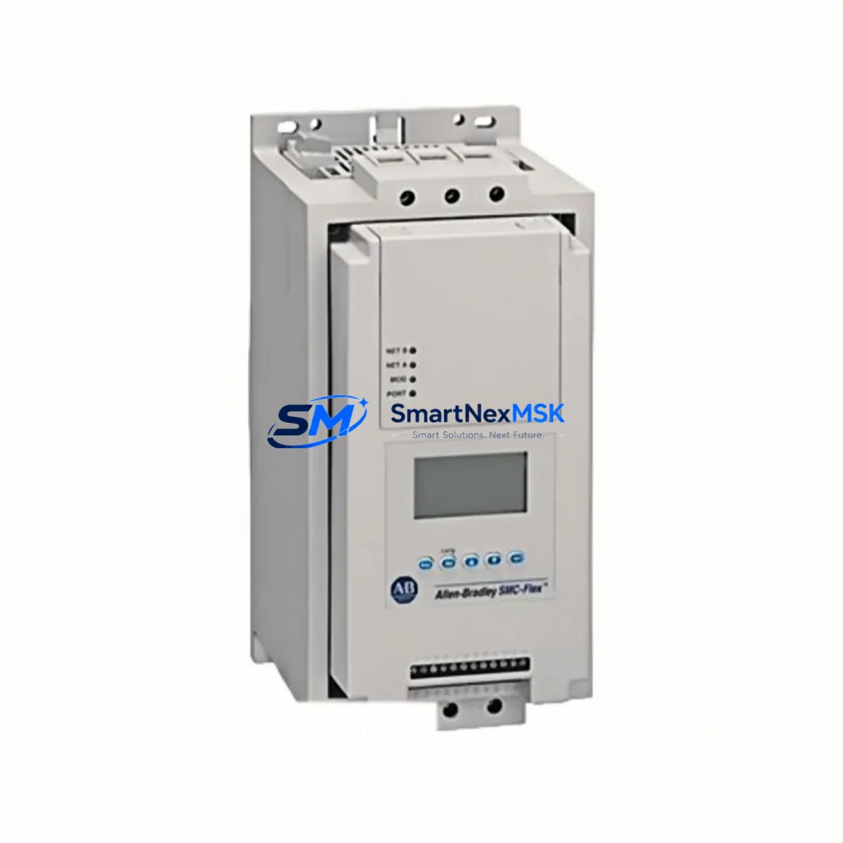
Allen-Bradley 150-F60NBRB Maintenance-Ready Spare for SMC-Flex Automation
The Allen-Bradley 150-F60NBRB is a 60A, 200–480V three-phase SMC-Flex Soft Starter designed for demanding industrial motor control applications. As a maintenance-ready original spare, this unit is sourced, inspected, and tested to support rapid field replacement and minimize unplanned downtime in manufacturing, process, and utilities environments. Whether you are managing a planned shutdown, responding to an emergency fault, or building out your critical spare parts inventory, the 150-F60NBRB delivers the compatibility, reliability, and documentation traceability that maintenance and procurement engineers require.
The SMC-Flex platform from Rockwell Automation is widely deployed across conveyor systems, pump stations, compressor drives, and HVAC motor circuits. When a soft starter fails in these environments, every minute of downtime translates directly into production loss. Stocking the 150-F60NBRB as a pre-qualified replacement unit eliminates the lead time risk associated with spot purchasing and ensures your team can execute a controlled swap-out within a single maintenance window.
Each unit shipped by SMARTNEXMSK undergoes functional verification prior to dispatch, is packaged to IEC transport standards, and is covered by a 12-month warranty against manufacturing defects. Long-term supply continuity is supported for legacy SMC-Flex installations where OEM availability may be constrained.
Spare Maintenance Table
| Parameter | Specification |
|---|---|
| Part Number / SKU | 150-F60NBRB |
| Brand / Manufacturer | Allen-Bradley (Rockwell Automation) |
| Series | SMC-Flex |
| Product Type | Solid-State Soft Starter |
| Rated Current | 60A |
| Supply Voltage | 200–480V AC, 3-Phase |
| Control Voltage | 100–240V AC (internal control supply) |
| Communication | DeviceNet / Remote I/O (per configuration) |
| Enclosure / Mounting | Open Type, Panel Mount |
| Protection Features | Motor overload, phase loss, undervoltage, jam detection |
| Compatibility | Direct replacement for SMC-Flex 60A frame; compatible with 1203-GU6, 1203-USB DeviceNet adapters |
| Application Environment | Industrial panel, MCC, pump/fan/conveyor motor circuits |
| Installation | DIN rail or panel mount; standard SMC-Flex wiring footprint |
| Origin | United States (Rockwell Automation OEM) |
| Condition | Original, tested before shipment |
| Warranty | 12 Months |
| Maintenance Recommendation | Inspect bypass contactor, control wiring, and DeviceNet node address before installation; verify firmware revision compatibility with existing PLC program |
Maintenance Planning for Continuous Operation
Replacing the 150-F60NBRB in the field is rarely an isolated task. A thorough maintenance engineer will treat the soft starter swap as an opportunity to audit the entire motor control circuit and adjacent components in the same control cabinet. Before energizing the replacement unit, inspect the bypass contactor — typically a 100-C or 700-CF series contactor — for contact wear and coil integrity. Verify that the 1492-SP or 1492-GH series branch circuit protection fuses or breakers upstream of the starter are within rated capacity and show no signs of thermal stress.
Check the 1756-IB16 or 1756-OB16 digital I/O modules in the associated ControlLogix or CompactLogix rack that handle the run/stop command and fault feedback signals for the soft starter. A degraded I/O channel can mask a genuine starter fault or prevent proper restart sequencing after replacement. Similarly, inspect the 1734-IB8 or 1734-OB8 POINT I/O modules if the motor circuit is managed through a distributed I/O drop.
For installations using DeviceNet communication, confirm that the 1203-GU6 DeviceNet communication module or the 1203-USB gateway is functioning correctly and that the node address on the replacement 150-F60NBRB matches the original configuration. A node address mismatch will prevent the PLC from recognizing the new unit and will generate a communication fault on the DeviceNet scanner — typically a 1756-DNB or 1769-SDN module.
Terminal blocks — particularly 1492-W3 or equivalent feed-through terminals — should be inspected for loose connections, discoloration, or insulation damage at the power and control wiring terminations. In high-cycle applications, terminal screws can back off over time and create intermittent faults that are difficult to diagnose without a physical inspection. If the control cabinet includes a 1606-XLP or 1606-XLS series power supply for the 24VDC control circuit, verify output voltage stability under load before commissioning the replacement starter.
For sites running older SMC-Flex installations alongside legacy PanelView 550 or PanelView Plus HMI terminals, confirm that the HMI faceplate logic references the correct device tag after any program download associated with the replacement. Proactively stocking a 150-F60NBRB alongside its associated bypass contactor, DeviceNet adapter, and a set of branch circuit fuses as a matched spare kit is a best practice that significantly reduces mean time to repair (MTTR) for motor control faults.
Site Replacement Workflow
Step 1 — Isolation and Lockout/Tagout: De-energize the motor circuit at the MCC or local disconnect. Apply LOTO per site procedure. Confirm zero energy state with a calibrated voltage tester at the L1/L2/L3 input terminals of the 150-F60NBRB.
Step 2 — Document Existing Configuration: Record the DeviceNet node address, parameter settings (ramp time, current limit, kick start settings), and any custom fault response configurations from the existing unit using RSNetWorx for DeviceNet or the handheld 193-DNENCAT parameter tool if available. Photograph all wiring terminations before disconnection.
Step 3 — Remove Faulty Unit: Disconnect power wiring (L1/L2/L3 input, T1/T2/T3 output), control wiring (terminals 1–6), and the DeviceNet drop cable. Remove the unit from its mounting position.
Step 4 — Install Replacement 150-F60NBRB: Mount the replacement unit. Reconnect all wiring per the original termination photograph. Set the DeviceNet node address to match the original. Restore parameter settings via RSNetWorx or the parameter module.
Step 5 — Pre-Energization Checks: Verify bypass contactor operation, control supply voltage (100–240V AC), and DeviceNet cable continuity. Confirm no ground faults on the motor circuit with an insulation resistance test.
Step 6 — Commission and Test: Energize the circuit. Confirm the PLC recognizes the device on the DeviceNet network. Execute a controlled motor start and verify ramp profile, current draw, and fault-free operation. Log the replacement in the site maintenance record.
This workflow is compatible with direct replacement of earlier SMC-Flex 60A variants and supports system continuity without PLC program modification in most standard configurations.
Spare Parts Support FAQ
Q1: Is the 150-F60NBRB a direct drop-in replacement for other SMC-Flex 60A models?
Yes. The 150-F60NBRB is dimensionally and electrically compatible with other SMC-Flex 60A frame variants within the 150-F series. Wiring footprint, mounting pattern, and DeviceNet interface are consistent across the frame size. Verify the control voltage range and communication option code (suffix) matches your existing installation before installation.
Q2: What testing is performed before shipment?
Each 150-F60NBRB unit supplied by SMARTNEXMSK undergoes functional verification including power-on self-test, control circuit continuity check, and communication interface validation where applicable. Units are packaged in anti-static, shock-protected packaging with a test record included in the shipment documentation.
Q3: How should the 150-F60NBRB be stored as a long-term spare?
Store in a dry, temperature-controlled environment (0–50°C, <95% RH non-condensing). Keep in original anti-static packaging. Avoid storage near strong magnetic fields or corrosive atmospheres. Inspect annually for any signs of capacitor degradation or connector oxidation. Recommended maximum storage period before commissioning is 5 years under proper conditions.
Q4: What is covered under the 12-month warranty?
The 12-month warranty covers manufacturing defects, component failure under normal operating conditions, and DOA (dead on arrival) units. It does not cover damage resulting from incorrect installation, overvoltage events, physical impact, or operation outside rated parameters. Warranty claims are processed with return authorization; SMARTNEXMSK provides replacement or repair at no charge for valid warranty cases.
© 2026 SMARTNEXMSK. All rights reserved.
Original Source: https://smartnexmsk.com
Contact: [email protected] | +86 18259474341



