
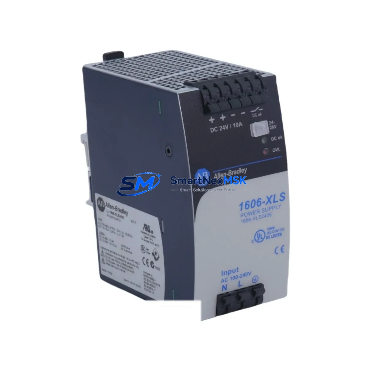
Allen-Bradley 1606-XLS240E Spare for 1606-XLS Automation: Spare Replacement & Industrial Downtime Risk Control
The Allen-Bradley 1606-XLS240E is a 240W, 24VDC DIN-rail mounted power supply engineered for continuous-duty industrial automation environments. As a maintenance-ready original spare, the 1606-XLS240E is designed to support rapid field replacement in control panels running Rockwell Automation ControlLogix, CompactLogix, MicroLogix, and PowerFlex drive systems. Whether you are managing a planned shutdown, responding to an unscheduled fault, or building a strategic spare parts inventory, stocking a verified 1606-XLS240E significantly reduces mean time to repair (MTTR) and protects production continuity.
For maintenance engineers and procurement engineers responsible for aging control infrastructure, the 1606-XLS240E represents a direct, pin-compatible replacement for earlier 1606-XLS series units. Its wide-range AC input (100–240VAC), regulated 24VDC output, and integrated active power factor correction make it suitable for both retrofit and greenfield panel builds. Each unit ships fully tested, with output voltage, ripple, and load regulation verified prior to dispatch.
Spare Maintenance Table
| Parameter | Specification |
|---|---|
| SKU / Part Number | 1606-XLS240E |
| Brand | Allen-Bradley (Rockwell Automation) |
| Series | 1606-XLS |
| Output Power | 240W |
| Output Voltage | 24VDC (adjustable 24–28V) |
| Output Current | 10A continuous |
| Input Voltage | 100–240VAC, 50/60Hz (universal input) |
| Mounting | DIN-rail (EN 60715 / TS 35) |
| Protection Class | IP20 |
| Operating Temperature | -25°C to +70°C |
| Efficiency | >93% typical |
| Certifications | UL 508, CE, cULus, ATEX Zone 2 |
| Compatibility | ControlLogix, CompactLogix, MicroLogix, PowerFlex, SLC 500 panels |
| Application Environment | Industrial control panels, MCC cabinets, process automation racks |
| Maintenance Recommendation | Inspect output terminals and load wiring annually; replace capacitors per OEM lifecycle guidance (typically 7–10 years) |
| Warranty | 12 Months |
| Origin | USA (Rockwell Automation) |
| Condition | Original Spare — New or Surplus New |
Maintenance Planning for Continuous Operation
When a 1606-XLS240E fails or is flagged during a routine control cabinet inspection, experienced maintenance engineers know that the power supply is rarely the only component that requires attention. A systematic inspection of the surrounding electrical circuit is essential to prevent repeat failures and ensure a clean restart.
Begin by verifying the upstream AC supply: check the circuit breaker rating and condition, and inspect the input wiring for signs of thermal stress or loose terminations. If the panel uses a 1606-XLSRED10 or 1606-XLSRED20 redundancy module to parallel two 1606-XLS units, inspect the redundancy module’s diode assembly and output bus connections simultaneously — a failed power supply often masks a degraded redundancy module that will cause the next unit to fail prematurely.
On the DC output side, inspect the 24VDC distribution terminal blocks (such as Phoenix Contact or Weidmüller DIN-rail terminal strips) for discoloration, loose screws, or corroded contacts. Downstream 24VDC fuse holders and blade fuses protecting individual I/O circuits should be tested under load. Any 1756-IB16 or 1756-OB16 ControlLogix I/O modules drawing power from this supply should be checked for proper seating and backplane connector integrity.
For panels incorporating a 1756-PA75 or 1756-PB75 ControlLogix power supply alongside the 1606-XLS240E (a common configuration where the PLC chassis has its own supply and the 24VDC field power is separate), verify that the chassis supply is independently healthy before concluding the 1606-XLS240E is the sole fault source.
Communication infrastructure in the same cabinet — including 1756-EN2T EtherNet/IP communication modules, 1756-DNB DeviceNet scanner cards, or PROFIBUS DP adapters — should be power-cycled cleanly after the replacement to clear any latched fault states. If the panel includes a PanelView Plus 7 HMI or a 2711P series operator terminal, confirm that the HMI’s 24VDC input is within tolerance after the new supply is commissioned.
Signal isolators and loop-powered transmitters connected to analog I/O modules (such as 1756-IF16 or 1756-OF8) are sensitive to supply voltage transients during replacement. Where possible, use a temporary 24VDC bench supply to maintain loop power during the changeover, preventing nuisance alarms and protecting field instruments. Surge protection devices (SPDs) on the 24VDC bus should also be inspected — a failed SPD can cause chronic power supply trips that are misdiagnosed as supply failures.
Site Replacement Workflow
Step 1 — Isolation and Lockout/Tagout: De-energize the panel per site LOTO procedures. Confirm zero energy state on both AC input and 24VDC output rails before opening the enclosure.
Step 2 — Documentation: Photograph the existing wiring layout, terminal assignments, and DIN-rail position of the 1606-XLS240E before removal. Note the output voltage trim setting if the unit has been adjusted from factory default.
Step 3 — Removal: Disconnect AC input wiring (L, N, PE) and 24VDC output wiring (+V, -V, PE). Release the DIN-rail latch and slide the unit off the rail. Retain all terminal screws and ferrules for reuse or replacement.
Step 4 — Inspection: Before installing the replacement 1606-XLS240E, inspect the DIN-rail section for deformation, corrosion, or loose mounting screws. Clean the rail contact surface if oxidation is present.
Step 5 — Installation: Clip the new 1606-XLS240E onto the DIN rail. Reconnect AC input and 24VDC output wiring to the same terminal positions. Torque terminal screws to the manufacturer’s specification (typically 0.5–0.6 Nm for this class of supply).
Step 6 — Commissioning: Restore AC power and measure output voltage at the supply terminals and at the furthest downstream load point. Confirm voltage is within 24–28VDC. Check output current under normal load conditions. Verify no fault LEDs are active on the supply or on downstream I/O modules.
Step 7 — System Restart: Perform a controlled PLC restart or fault reset as required by the site’s restart procedure. Confirm all I/O, communications, and HMI screens return to normal operating state before releasing the system to production.
This workflow is compatible with direct replacement of earlier 1606-XLS series units including the 1606-XLS120E and 1606-XLS480E, maintaining full system compatibility without firmware or configuration changes.
Spare Parts Support FAQ
Q1: Is the 1606-XLS240E still available as a new original spare, or is it discontinued?
The 1606-XLS240E remains available as an original spare through authorized industrial distributors and specialist spare parts suppliers. While Rockwell Automation periodically updates its active product portfolio, surplus-new and factory-sealed units continue to be sourced to support legacy panel maintenance. Each unit we supply is verified for authenticity and tested prior to shipment.
Q2: How do I confirm compatibility before ordering?
Compatibility is confirmed by matching the output voltage (24VDC), output power (240W), and DIN-rail mounting format to your existing installation. The 1606-XLS240E is a direct form-fit-function replacement for other 1606-XLS series units of the same power rating. If your panel uses a redundancy module, confirm the module’s maximum input current rating accommodates the 1606-XLS240E’s 10A output. Contact our technical team with your panel drawing or existing part number for a pre-order compatibility check.
Q3: What testing is performed before shipment?
Every 1606-XLS240E is bench-tested under load prior to dispatch. Testing includes output voltage verification at no-load and full-load, output ripple measurement, and functional check of all protection circuits (overcurrent, overvoltage, short-circuit). A test report is available upon request. Units are shipped in anti-static packaging with original or equivalent protective inserts.
Q4: What does the 12-month warranty cover?
The 12-month warranty covers defects in materials and workmanship under normal operating conditions. It includes free replacement or repair of any unit that fails within the warranty period due to manufacturing defects. The warranty does not cover damage caused by incorrect installation, overvoltage events, physical damage, or operation outside the specified environmental ratings. Warranty claims are processed within 5 business days of receipt of the returned unit.
© 2026 SMARTNEXMSK. All rights reserved.
Original Source: https://smartnexmsk.com
Contact: [email protected] | +86 18259474341



