
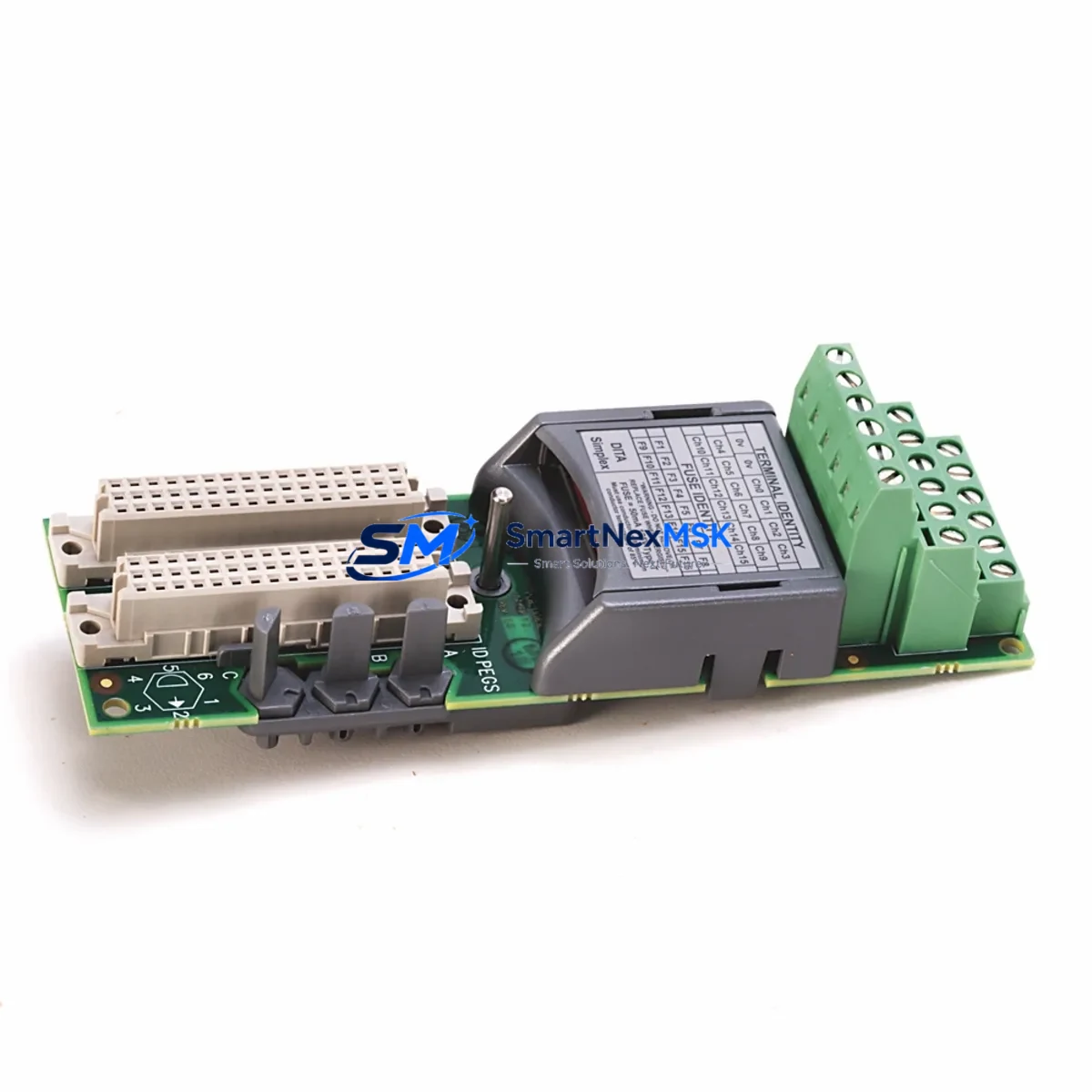
Allen-Bradley 1715-TASIB16D Retrofit-Ready Digital Input Assembly: Compatible Modernization for 1715 Redundant I/O Control Systems
The Allen-Bradley 1715-TASIB16D is a 16-channel digital input termination assembly engineered for the 1715 Redundant I/O platform — one of Rockwell Automation’s most widely deployed safety-rated distributed I/O architectures. As legacy control systems age and original spare parts become increasingly difficult to source, the 1715-TASIB16D serves as a verified retrofit-ready replacement that enables smooth migration from discontinued termination assemblies without requiring backplane redesign, rewiring, or PLC program modification.
This module is designed to interface directly with the 1715-IB16D dual-port 16-channel digital input module, maintaining the same terminal block layout, field wiring pitch, and connector keying as the original assembly. Engineers undertaking a control cabinet upgrade or redundant I/O expansion can install the 1715-TASIB16D into an existing 1715 chassis without altering the field wiring schedule — a critical advantage when minimizing planned downtime windows in continuous-process environments such as oil and gas, chemical processing, and power generation.
Upgrade Compatibility Table
| Parameter | Detail |
|---|---|
| SKU / Part Number | 1715-TASIB16D |
| Compatible I/O Module | 1715-IB16D (16-Ch Digital Input, Dual-Port) |
| Platform | Allen-Bradley 1715 Redundant I/O System |
| Channel Count | 16 Digital Input Channels |
| Backplane Interface | 1715 Series Chassis (1715-A2, 1715-A3 compatible) |
| Terminal Block Type | Removable screw-type, field-side wiring retained on swap |
| Communication Compatibility | EtherNet/IP via 1715-AENTR Adapter; no protocol change required |
| Replacement Recommendation | Direct drop-in for discontinued or damaged 1715-TASIB16D units |
| Installation Requirement | No backplane modification; field wiring reuse supported |
| Commissioning Note | Verify module address assignment in Studio 5000 after installation |
| Warranty | 12-Month Warranty — covers manufacturing defects and functional failure |
Retrofit Planning for Existing Automation Systems
Successful integration of the 1715-TASIB16D into an aging control system requires a structured pre-installation assessment. Before removing the existing termination assembly, engineers should document the current field wiring schedule and confirm that the terminal block on the replacement unit matches the original pinout. In most 1715 Redundant I/O installations, the termination assembly is the field-side interface that remains in place while the I/O module itself is hot-swapped — this architecture means the 1715-TASIB16D can often be pre-wired and tested before the actual cutover begins.
Power supply capacity is a key verification point. The 1715 system draws power from the 1715-PS1 or 1715-PS2 redundant power supply modules mounted in the 1715 chassis. Before adding or replacing termination assemblies, confirm that the combined current draw of all installed I/O modules — including the 1715-OB16D digital output modules, 1715-IF16 analog input modules, and any 1715-OF8I analog output modules in the same rack — does not exceed the rated output of the installed power supply pair. Overloading the backplane power bus is a common cause of intermittent faults during retrofit projects.
The 1715-AENTR EtherNet/IP adapter module governs communication between the 1715 chassis and the ControlLogix or GuardLogix controller. When replacing a termination assembly, the adapter’s configuration in Studio 5000 Logix Designer does not need to be modified, provided the replacement module occupies the same slot and carries the same module definition. However, if the retrofit involves relocating the 1715-IB16D to a different slot within the 1715-A2 or 1715-A3 chassis, the module address must be updated in the controller project and the I/O tree re-downloaded to the 1715-AENTR. Failure to update the slot address is one of the most frequent commissioning errors in 1715 retrofit projects.
For sites migrating from older 1756 ControlLogix I/O modules to the 1715 Redundant I/O platform, the transition typically involves replacing 1756-IB16 or 1756-IB32 digital input modules with the 1715-IB16D and its associated 1715-TASIB16D termination assembly. This migration path requires a new Add-On Profile (AOP) to be imported into Studio 5000, and the existing ladder logic or function block routines referencing the old I/O tags must be remapped to the new 1715 tag structure. HMI screens built in FactoryTalk View SE or FactoryTalk View ME that display field device status will also require tag path updates to reflect the new I/O module addressing.
In control cabinet upgrades where space is constrained, the compact form factor of the 1715 chassis — particularly the 1715-A2 two-slot chassis — allows the 1715-TASIB16D and its paired input module to be installed in a DIN-rail mounted enclosure alongside the 1715-AENTR adapter and the 1715-PS1 power supply, minimizing the footprint impact of the redundant I/O upgrade. All units supplied by SMARTNEXMSK are pre-tested for functional integrity and shipped with full documentation to support site acceptance testing.
Downtime Control During System Migration
Minimizing unplanned downtime is the primary operational constraint in any live-system retrofit. The 1715 Redundant I/O architecture is specifically designed to support online module replacement — the redundant backplane allows one I/O path to remain active while the other is serviced. When replacing the 1715-TASIB16D, the recommended procedure is to place the associated 1715-IB16D module into inhibited mode within Studio 5000 before disconnecting field wiring, ensuring that the controller continues executing its scan cycle without generating fault codes for the affected input channel group.
Before beginning the physical swap, export a backup of the current controller project from Studio 5000 and save a copy of the 1715-AENTR adapter configuration. This preserves the original program logic, I/O tag assignments, and module parameters, allowing rapid restoration if the replacement procedure encounters an unexpected issue. For sites running GuardLogix safety controllers, the safety task signature must be re-verified after any I/O configuration change — plan for this step in the commissioning schedule to avoid delays during the post-installation functional safety test.
Field wiring continuity should be verified with a loop test on all 16 input channels before the inhibit is removed and the module is returned to active scan. This step confirms that the terminal block connections on the new 1715-TASIB16D are correctly seated and that no field wiring was disturbed during the swap. Once the loop test is complete, remove the inhibit in Studio 5000, confirm that all 16 channels report the expected states in the I/O diagnostics view, and document the completion time for the maintenance record. Total planned downtime for a single termination assembly replacement in a well-prepared 1715 system is typically under 30 minutes.
Retrofit Support FAQ
Q1: Is the 1715-TASIB16D a direct replacement for my existing unit without rewiring?
Yes. The 1715-TASIB16D uses the same removable terminal block design as the original assembly. Field wiring attached to the terminal block can be disconnected as a single unit and reconnected to the replacement assembly without disturbing individual wire terminations, provided the terminal block itself is undamaged. Confirm the terminal block part number matches before proceeding.
Q2: Do I need to modify my Studio 5000 project after installing the replacement?
Not if the replacement occupies the same chassis slot as the original. The module definition, I/O tags, and controller program remain valid. If the slot position changes, update the module address in the I/O tree and re-download the configuration to the 1715-AENTR adapter. Always perform a full functional test after any configuration change.
Q3: What pre-shipment testing is performed on the 1715-TASIB16D?
Each unit supplied by SMARTNEXMSK undergoes functional verification prior to dispatch, including terminal block continuity checks and visual inspection for physical damage. Units are shipped with protective packaging to prevent transit damage. A 12-month warranty covers manufacturing defects and functional failure from the date of shipment.
Q4: Can this termination assembly be used with both ControlLogix and GuardLogix controllers?
Yes. The 1715-TASIB16D is compatible with both standard ControlLogix and safety-rated GuardLogix controller platforms when paired with the 1715-IB16D input module and the 1715-AENTR EtherNet/IP adapter. For GuardLogix applications, ensure that the safety task configuration and safety I/O connection parameters are validated as part of the post-installation functional safety verification procedure.
© 2026 SMARTNEXMSK. All rights reserved.
Original Source: https://smartnexmsk.com
Contact: [email protected] | +86 18259474341



