
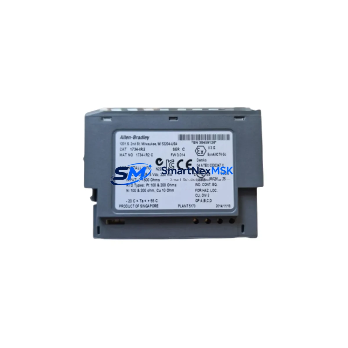
Allen-Bradley 1734-IR2 Retrofit-Ready RTD Input for POINT I/O Systems
The Allen-Bradley 1734-IR2 is a 2-channel RTD (Resistance Temperature Detector) input module engineered for the POINT I/O 1734 series platform. As legacy distributed I/O systems age and original spare parts become increasingly difficult to source, the 1734-IR2 serves as a direct, retrofit-ready replacement for discontinued RTD input modules across a wide range of Allen-Bradley control architectures. Whether you are upgrading an aging ControlLogix or CompactLogix system, migrating from an older SLC 500 or PLC-5 distributed I/O network, or restoring a failed node in an existing POINT I/O rack, the 1734-IR2 delivers the signal accuracy, backplane compatibility, and firmware alignment required for a smooth, low-risk transition.
The module supports PT100, PT1000, Ni120, and 10Ω copper RTD sensor types, providing broad flexibility for temperature measurement applications in process control, HVAC, food and beverage, and industrial manufacturing environments. Its compact DIN-rail-mounted form factor integrates directly into the 1734 POINT I/O backplane without requiring additional adapter hardware, making it an efficient choice for control cabinet upgrades where space and downtime are critical constraints.
When planning a retrofit around the 1734-IR2, engineers should verify the power budget of the existing 1734-EP24DC or 1734-EPAC power supply module. Each POINT I/O segment has a defined backplane current capacity, and adding or replacing I/O modules requires confirming that the total module draw does not exceed the supply rating. In most standard retrofit scenarios, the 1734-IR2 draws approximately 75 mA from the backplane, consistent with the original module it replaces.
Terminal wiring compatibility is another key verification step. The 1734-IR2 uses the standard 1734-TOPS or 1734-TOPS2 removable terminal block, which allows technicians to pre-wire the replacement module before powering down the system. This wiring-forward approach significantly reduces live exposure time and supports a faster, safer swap during planned maintenance windows. Confirm that existing field wiring for 2-wire, 3-wire, or 4-wire RTD configurations matches the channel assignment in the original program before finalizing the terminal layout.
Upgrade Compatibility Table
| Parameter | Detail |
|---|---|
| Module SKU | 1734-IR2 |
| Series | Allen-Bradley POINT I/O 1734 |
| Channels | 2-Channel RTD Input |
| Supported Sensors | PT100, PT1000, Ni120, 10Ω Copper RTD |
| Backplane Interface | 1734 POINT I/O Backplane (direct mount, no adapter required) |
| Terminal Block | 1734-TOPS / 1734-TOPS2 (removable, pre-wireable) |
| Backplane Current Draw | ~75 mA |
| Compatible Controllers | ControlLogix 1756, CompactLogix 1769, SoftLogix |
| Communication Adapter | 1734-AENT (EtherNet/IP), 1734-ADN (DeviceNet), 1734-APB (PROFIBUS) |
| Replacement Compatibility | Direct drop-in for discontinued 1734-series RTD input modules; replaces legacy 1746-NR4 and 1771-IR in migration projects |
| Installation Requirement | DIN rail mount; slot-based address auto-assigned by backplane position |
| Programming Environment | RSLogix 5000 / Studio 5000 Logix Designer |
| HMI Compatibility | FactoryTalk View SE / ME (tag path update required on migration) |
| Commissioning Note | Verify 1734-AENT firmware ≥ 3.x before enumeration; bench-test recommended prior to cutover |
| Warranty | 12-Month Warranty from date of shipment; pre-shipment functional testing included |
Retrofit Planning for Existing Automation Systems
A successful retrofit centered on the 1734-IR2 begins with a full audit of the existing POINT I/O segment. Technicians should document the current slot assignments across the 1734 backplane, noting the position of each module — including analog output modules such as the 1734-OE2V or 1734-OE4C, digital input modules like the 1734-IB8, and specialty modules such as the 1734-SSI for encoder feedback. This slot map becomes the reference for module address configuration in Studio 5000 Logix Designer, where each POINT I/O module is identified by its physical slot position rather than a manually assigned node address.
The communication adapter connecting the POINT I/O segment to the controller — most commonly the 1734-AENT for EtherNet/IP networks — should be inspected for firmware version compatibility with the replacement module. In systems where the adapter firmware predates the 1734-IR2’s release, a firmware update may be required before the module will enumerate correctly on the network. This step is particularly important in older installations where the 1734-AENT was originally commissioned with firmware versions below 3.x.
For systems migrating from legacy SLC 500 or PLC-5 platforms to a ControlLogix or CompactLogix architecture, the 1734-IR2 can serve as the RTD input component in a new distributed I/O segment, replacing older 1746-NR4 or 1771-IR analog input modules. In these migration scenarios, the control program must be re-mapped to reference the new module’s tag structure in Studio 5000, and any HMI screens built in FactoryTalk View SE or FactoryTalk View ME will require tag path updates to reflect the new controller and I/O tree. Pre-staging the replacement module on a bench test rack — using a 1734-AENT adapter and a temporary 24VDC power supply — allows engineers to validate the module’s channel configuration and RTD sensor readings before the scheduled cutover.
Control cabinet upgrades that incorporate the 1734-IR2 alongside a new 1756-L85E ControlLogix controller and 1756-EN2T EtherNet/IP communication module should also account for the 1734-EP24DC power supply’s position in the segment. If the retrofit adds more than two or three new I/O modules to an existing segment, splitting the segment with an additional power supply module is recommended to maintain stable backplane voltage under full load. Programming cables such as the 1784-U2DHP USB-to-DH+ adapter may also be needed when connecting to older controller backplanes during the transition phase.
Downtime Control During System Migration
Minimizing unplanned downtime during a POINT I/O retrofit requires a structured cutover plan that preserves the original control logic and field wiring integrity throughout the transition. The recommended approach is to pre-wire the 1734-IR2 using a spare 1734-TOPS terminal block, configure the module’s channel parameters offline in Studio 5000 using the existing project file, and download the updated program to the controller during a planned maintenance window — without modifying any other rungs or routines in the ladder logic.
Before removing the failed or obsolete module, technicians should place the controller in Program mode and record the current process values from the RTD channels using the controller’s online tag monitor. This snapshot serves as a baseline for verifying that the replacement module is reading correctly after installation. Once the 1734-IR2 is seated in the backplane and the terminal block is connected, the controller can be returned to Run mode. The module will enumerate automatically based on its slot position, and the existing tag references in the program will map to the new module without requiring a full program download in most cases.
For systems where the RTD inputs feed critical PID loops or safety interlocks, it is advisable to temporarily place those loops in manual mode or bypass the interlock logic during the swap interval. This prevents nuisance trips or uncontrolled process responses during the brief period when the module is offline. Once the 1734-IR2 is confirmed online and reading within expected temperature ranges, the loops can be returned to automatic control and the interlock logic re-enabled. Total swap time for a single 1734-IR2 module in a well-prepared retrofit is typically under 15 minutes, keeping production impact to a minimum.
Retrofit Support FAQ
Q: Is the 1734-IR2 a direct replacement for my existing POINT I/O RTD input module?
A: Yes. The 1734-IR2 is designed as a direct drop-in replacement for compatible 1734-series RTD input modules. It uses the same backplane connector, the same removable terminal block interface (1734-TOPS / 1734-TOPS2), and the same slot-based addressing scheme. No hardware adapter or backplane modification is required. Verify that your existing Studio 5000 project file includes the 1734-IR2 module definition, or add it from the module catalog before downloading the updated program.
Q: What wiring changes are needed when replacing an older RTD input module with the 1734-IR2?
A: In most cases, no field wiring changes are required if the original module used the same terminal block type. The 1734-TOPS removable terminal block can be transferred directly from the old module to the new 1734-IR2, preserving all existing field connections. If the original module used a different terminal block variant, re-termination will be necessary. Always verify the channel-to-terminal mapping in the 1734-IR2 installation manual before powering up to confirm that 2-wire, 3-wire, or 4-wire RTD connections are correctly assigned.
Q: How do I verify that the 1734-IR2 is communicating correctly after installation?
A: After seating the module and reconnecting the terminal block, go online with the controller in Studio 5000 and navigate to the I/O tree. The 1734-IR2 should appear with a green status indicator. Open the module’s input data tags and confirm that the channel values are reading within the expected temperature range for the connected RTD sensors. If the module shows a fault, check the 1734-AENT adapter firmware version and confirm that the module definition in the project matches the installed hardware revision. Pre-shipment functional testing on all units supplied by SMARTNEXMSK ensures the module arrives verified and ready for installation.
Q: What warranty coverage is included with the 1734-IR2?
A: All 1734-IR2 modules supplied by SMARTNEXMSK are covered by a 12-Month Warranty from the date of shipment. Each unit undergoes pre-shipment functional testing to verify channel accuracy, backplane communication, and terminal block integrity. If a module fails within the warranty period under normal operating conditions, SMARTNEXMSK will arrange a replacement or repair at no additional cost. Contact our technical support team with your order reference and a description of the fault for warranty claim processing.
© 2026 SMARTNEXMSK. All rights reserved.
Original Source: https://smartnexmsk.com
Contact: [email protected] | +86 18259474341



