
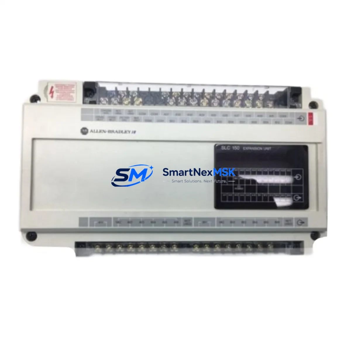
Allen-Bradley 1745-E102 Retrofit-Ready I/O Expansion for SLC 150 Control Systems
The Allen-Bradley 1745-E102 is a discrete I/O expansion module engineered for the SLC 150 programmable controller platform — one of the most widely deployed small-format PLCs in legacy manufacturing, material handling, and process control environments. As the SLC 150 series has reached end-of-life status, sourcing verified replacement modules has become a critical challenge for maintenance engineers and system integrators managing aging control infrastructure. SMARTNEXMSK maintains ready stock of the 1745-E102 to support planned retrofits, emergency replacements, and phased system upgrades without forcing a full platform migration.
Whether you are replacing a failed module on an active production line, building a spare-parts buffer for a multi-site SLC 150 installation, or planning a staged migration toward a MicroLogix 1100 or MicroLogix 1400 architecture, the 1745-E102 provides a direct, wiring-compatible path that preserves your existing I/O addressing, terminal block layout, and ladder logic program structure. This eliminates the need for immediate software rewrites or panel rewiring — two of the most time-consuming and risk-prone elements of any control system upgrade.
Upgrade Compatibility Table
| Parameter | Detail |
|---|---|
| Module SKU | 1745-E102 |
| Compatible Platform | Allen-Bradley SLC 150 (1745 Series) |
| Module Type | Discrete I/O Expansion |
| Backplane Interface | SLC 150 proprietary expansion bus |
| Terminal Compatibility | Direct drop-in; matches OEM terminal block pitch and wiring layout |
| Communication Protocol | SLC 150 native I/O bus (no Ethernet/IP or DH+ required) |
| Replacement Recommendation | Direct replacement for failed or end-of-life 1745-E102 units |
| Migration Path | Compatible with staged migration to MicroLogix 1100 / 1400 with I/O remapping |
| Commissioning Notes | Verify module address jumpers; confirm I/O map in RSLogix 500 or APS software |
| Warranty | 12 Months — covers manufacturing defects and functional failure under normal operating conditions |
Retrofit Planning for Existing Automation Systems
A successful 1745-E102 retrofit begins well before the module arrives on site. Engineers should start by auditing the existing 1745-L1 or 1745-L2 SLC 150 processor to confirm firmware revision compatibility and available expansion slots. The 1745-E102 occupies one expansion slot on the SLC 150 backplane, and the total I/O count — including the base unit and all expansion modules — must remain within the processor’s addressing limits.
Terminal block wiring should be documented before removal of the failed module. Photograph or sketch the field wiring connections, noting wire color, terminal number, and signal type (discrete input, discrete output, 24VDC, or 120VAC). The 1745-E102 uses a removable terminal block on most revisions, which simplifies swap-out without disturbing field wiring. Confirm that the replacement unit’s terminal block revision matches the installed base before proceeding.
For sites running the original APS (Advanced Programming Software) on DOS-based workstations, or those that have migrated to RSLogix 500 on Windows, the I/O configuration file should be backed up prior to any hardware change. The module address — set via onboard DIP switches or jumpers on the 1745-E102 — must match the address assigned in the program. A mismatch will result in a major fault on the 1745-L1 processor at power-up.
Sites planning a longer-term migration to a MicroLogix 1100 or CompactLogix L16ER platform should use the 1745-E102 replacement as an opportunity to document the full I/O schedule, including signal descriptions, PLC addresses, and HMI tag cross-references. This documentation will be essential when remapping I/O in RSLogix 500 or Studio 5000 during the eventual platform transition. If the site uses a PanelView 300 or PanelView 550 HMI connected to the SLC 150 via DH-485, the communication link and tag database should be verified after module replacement to ensure screen updates and alarm setpoints remain intact.
Power supply capacity is another critical checkpoint. The SLC 150 system draws power from the 1745-P1 or equivalent power supply module. Adding or replacing an expansion module changes the backplane current draw. Verify that the installed power supply can support the full complement of I/O modules — including the 1745-E102 — without exceeding its rated output. If the power budget is marginal, consider upgrading to a higher-capacity supply as part of the retrofit scope.
For multi-rack or distributed I/O configurations, also verify that any 1747-AIC isolated link coupler or 1747-KE DH-485/RS-232C interface modules remain properly addressed and terminated after the expansion module swap. Communication interruptions on the DH-485 network can cause cascading faults across connected devices, including remote I/O adapters and operator terminals.
Downtime Control During System Migration
Minimizing unplanned downtime is the primary concern for any maintenance team managing a live SLC 150 installation. The 1745-E102 replacement procedure is designed to be completed during a scheduled maintenance window, typically within two to four hours when proper preparation has been completed in advance.
Before initiating the swap, place the SLC 150 processor in Program mode using the keyswitch on the 1745-L1 or 1745-L2 unit. This suspends output scanning and prevents unintended actuator movement during the hardware change. Do not power down the entire panel unless required by site safety procedures — maintaining power to the backplane allows you to verify the new module’s status LEDs immediately after installation without a full system restart cycle.
Once the 1745-E102 is seated and the terminal block is reconnected, return the processor to Run mode and monitor the I/O status display in RSLogix 500 or APS. All input and output bits associated with the replacement module should reflect field device states within one scan cycle. If any bits remain in fault, recheck the module address jumper settings and confirm that the terminal block is fully engaged on the module connector.
For sites where a cold restart is unavoidable, ensure that the program file — stored in battery-backed RAM on the 1745-L1 or in EEPROM on later revisions — is intact before power-up. A corrupted or missing program file will result in a fault condition that requires reloading from the programming workstation. Keeping a current backup of the .RSS or .SLC program file on a dedicated laptop or USB drive at the panel is strongly recommended as part of any retrofit support kit.
SMARTNEXMSK pre-tests all 1745-E102 units prior to shipment, including functional I/O verification and backplane communication checks, to reduce the risk of receiving a non-functional module during a time-critical repair. Units are shipped with original-style packaging and include a test report confirming pass status before dispatch.
Retrofit Support FAQ
Q: Is the 1745-E102 a direct drop-in replacement for the original Allen-Bradley unit?
A: Yes. The 1745-E102 supplied by SMARTNEXMSK is functionally equivalent to the original Allen-Bradley production unit. It uses the same backplane connector, terminal block layout, and module address configuration. No program changes are required for a like-for-like replacement in an existing SLC 150 system.
Q: What commissioning steps are required after installing the replacement module?
A: After seating the module and reconnecting field wiring, verify that the module address jumpers match the address assigned in the PLC program. Power up the system and confirm I/O status in RSLogix 500 or APS. Check that all input bits reflect field device states and that output commands are executing correctly. If a DH-485 HMI is connected, verify that screen data is updating normally.
Q: Can the 1745-E102 be used as part of a migration to MicroLogix or CompactLogix?
A: The 1745-E102 is a SLC 150-specific module and is not directly compatible with MicroLogix or CompactLogix backplanes. However, using it as a short-term replacement allows production to continue while a full migration plan — including I/O remapping, HMI tag updates, and communication reconfiguration — is developed and tested offline. This staged approach significantly reduces migration risk and total downtime.
Q: What does the 12-month warranty cover?
A: The 12-month warranty covers manufacturing defects and functional failure under normal operating conditions from the date of shipment. It includes free replacement or repair of any unit confirmed defective within the warranty period. Units showing damage from incorrect installation, overvoltage, or environmental exposure outside the module’s rated specifications are not covered. Contact [email protected] to initiate a warranty claim.
© 2026 SMARTNEXMSK. All rights reserved.
Original Source: https://smartnexmsk.com
Contact: [email protected] | +86 18259474341



