
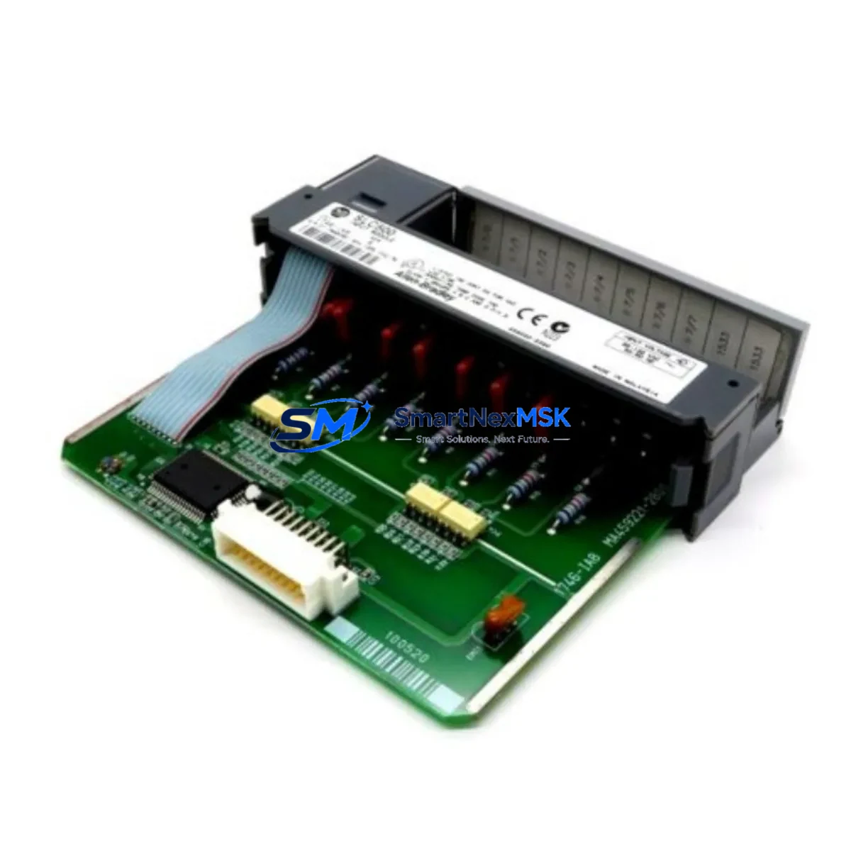
Allen-Bradley 1746-IA8 Retrofit-Ready AC Input for SLC 500 Control Systems
The Allen-Bradley 1746-IA8 is an 8-point, 120V AC discrete input module designed for the SLC 500 modular I/O platform. As legacy SLC 500 systems approach end-of-life and original spare parts become increasingly difficult to source, the 1746-IA8 remains one of the most critical retrofit components for engineers managing aging production lines, control cabinet upgrades, and field system recoveries. Whether you are replacing a failed module on an active line or pre-staging inventory for a planned shutdown, the 1746-IA8 delivers direct form-fit-function compatibility with existing SLC 500 racks and backplane wiring.
Each unit shipped by SMARTNEXMSK undergoes pre-shipment functional testing to verify input channel integrity, backplane communication, and terminal block continuity. All units are covered by a 12-month warranty from the date of shipment, giving procurement and maintenance teams confidence in both quality and supply continuity.
Upgrade Compatibility Table
| Parameter | Detail |
|---|---|
| SKU | 1746-IA8 |
| Series | SLC 500 |
| Input Points | 8-point discrete AC input |
| Input Voltage | 74–132V AC, 47–63 Hz |
| Backplane Interface | SLC 500 modular I/O backplane (1746 series) |
| Rack Compatibility | 1746-A4, 1746-A7, 1746-A10, 1746-A13 racks |
| Terminal Block | Removable screw-type, field-wiring compatible |
| Communication | SLC 500 backplane protocol (native) |
| Replacement Fit | Direct drop-in for 1746-IA8 (same slot, same wiring) |
| Commissioning Note | Verify I/O module address in RSLogix 500 after installation |
| Warranty | 12-Month Warranty from shipment date |
Retrofit Planning for Existing Automation Systems
When integrating the 1746-IA8 into an existing SLC 500 system, the retrofit process typically begins with a full audit of the control cabinet. Engineers should confirm the power supply capacity of the installed 1746-P4 or 1746-P7 power supply module, as adding or replacing I/O modules affects the total backplane current draw. The 1746-IA8 draws 75mA from the 5V backplane bus — a figure that must be factored into the rack’s total load budget alongside other installed modules such as the 1746-OB16 output module or 1746-NI8 analog input module.
Terminal block wiring should be documented before removal of the failed module. The 1746-IA8 uses a removable terminal block, which simplifies field replacement: the existing wiring harness can be transferred directly to the new module without re-termination, significantly reducing the risk of wiring errors and shortening commissioning time. Confirm that field device voltage levels (typically 120V AC from limit switches, proximity sensors, or push-button stations) fall within the module’s rated input range of 74–132V AC.
Backplane slot assignment must be verified in the RSLogix 500 program. The processor — commonly a 1747-L532 or 1747-L543 SLC 5/03 or SLC 5/04 CPU — maps each I/O slot to a specific file address. If the replacement 1746-IA8 is installed in the same physical slot as the original, no program changes are required. However, if the slot position changes due to rack reconfiguration, the I/O address mapping in the ladder logic must be updated accordingly, and any associated HMI screens built on PanelView 550 or PanelView 600 terminals will need tag address corrections to maintain accurate status display.
For systems that include a 1747-SDN DeviceNet Scanner or a 1747-KE RS-232 communication module, verify that the communication link remains unaffected by the I/O module swap. In most SLC 500 configurations, discrete I/O modules like the 1746-IA8 operate independently of the communication backplane, so protocol migration is not required. However, if the retrofit is part of a broader upgrade that includes migrating from DH-485 to EtherNet/IP, the addition of a 1761-NET-ENI network interface module or a 1747-AENTR EtherNet/IP adapter should be planned in parallel to avoid a second maintenance window.
Programming cable access is also a consideration during commissioning. A 1747-UIC USB-to-DH-485 interface cable is recommended for connecting a laptop running RSLogix 500 to the SLC processor during on-site verification. After installation, perform a forced I/O test on each of the 8 input channels to confirm that field signals are correctly read by the processor before returning the line to production.
Downtime Control During System Migration
Minimizing unplanned downtime is the primary concern for any maintenance team performing a 1746-IA8 replacement on a live production system. The recommended approach is to pre-stage the replacement module before the scheduled maintenance window: verify the module’s part number, inspect the terminal block for physical damage, and confirm firmware compatibility with the installed SLC processor version.
Where possible, schedule the swap during a planned production break or shift changeover. The physical replacement of a 1746-IA8 in a powered-down rack takes approximately 5–10 minutes. The processor program does not need to be re-downloaded if the slot address is unchanged — the SLC 500 CPU retains the program in battery-backed RAM (supported by the 1747-BA battery module), so the existing ladder logic, data files, and I/O configuration remain intact after power restoration.
Before powering the rack back on, perform a visual inspection of the backplane connector on the new module and confirm that the terminal block is fully seated. After power-up, monitor the module’s status LED: a solid green indicates normal operation, while a flashing or red LED indicates a fault condition that must be diagnosed via RSLogix 500 before resuming production. Document the replacement event in the site maintenance log, including the module serial number, installation date, and technician name, to support the 12-month warranty claim process if required.
For facilities managing multiple SLC 500 racks across a plant floor, maintaining a small buffer stock of 1746-IA8 modules reduces mean time to repair (MTTR) and eliminates the risk of extended downtime caused by supply chain delays. SMARTNEXMSK maintains ready inventory of the 1746-IA8 and can support urgent shipment requirements with same-day dispatch for in-stock orders.
Retrofit Support FAQ
Q: Is the 1746-IA8 a direct replacement for an existing failed module in my SLC 500 rack?
A: Yes. The 1746-IA8 is a direct form-fit-function replacement. It installs in the same backplane slot, uses the same removable terminal block wiring, and requires no program changes if installed in the same slot position. Verify the I/O address in RSLogix 500 after installation as a standard commissioning step.
Q: What wiring checks should I perform before installing the replacement module?
A: Confirm that all field device voltages are within the 74–132V AC input range. Photograph or document the existing terminal block wiring before removal. Transfer the removable terminal block from the old module to the new one to preserve wiring integrity. Check for any signs of terminal corrosion or insulation damage before re-energizing.
Q: How do I verify the module is functioning correctly after installation?
A: After power-up, check the module status LED for solid green. Use RSLogix 500 to monitor the I/O status bits for each of the 8 input channels. Perform a forced input test by activating each field device individually and confirming the corresponding bit toggles in the processor data file. This confirms both the field wiring and the backplane communication are operating correctly.
Q: What does the 12-month warranty cover, and how do I make a claim?
A: The 12-month warranty covers manufacturing defects and functional failures under normal operating conditions. It does not cover damage caused by incorrect installation, overvoltage, or physical mishandling. To initiate a warranty claim, contact SMARTNEXMSK with the module serial number, purchase order reference, and a description of the fault. Replacement or repair will be arranged within the warranty period.
© 2026 SMARTNEXMSK. All rights reserved.
Original Source: https://smartnexmsk.com
Contact: [email protected] | +86 18259474341



