
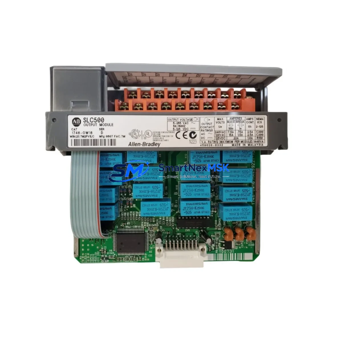
Allen-Bradley 1746-OW16/C Spare for SLC 500 Automation: Relay Output Replacement & Downtime Risk Control
The Allen-Bradley 1746-OW16/C is a 16-point relay output module designed for the SLC 500 modular chassis platform. As a maintenance-ready spare, it is a critical component in any industrial control cabinet stocking strategy. Relay output modules are among the highest-wear items in a PLC system — contact degradation, coil fatigue, and arc erosion from inductive loads make proactive replacement essential for continuous operation. Keeping a verified original 1746-OW16/C on the shelf eliminates the most common cause of unplanned downtime in SLC 500-based automation lines.
This module supports both AC and DC load switching across all 16 output points, with each relay rated for resistive and inductive loads typical of motor starters, solenoid valves, and pilot lights. It slots directly into any 1746 modular chassis — including the 1746-A4, 1746-A7, 1746-A10, and 1746-A13 — without firmware changes or re-configuration, making site replacement fast and low-risk. All units are tested prior to shipment and backed by a 12-month warranty.
Spare Maintenance Table
| Parameter | Specification |
|---|---|
| SKU / Part Number | 1746-OW16/C |
| Brand | Allen-Bradley (Rockwell Automation) |
| Series | SLC 500 / 1746 |
| Module Type | 16-Point Relay Output Module |
| Output Points | 16 (isolated relay contacts) |
| Load Voltage Range | 5–265V AC/DC |
| Max Load Current | 2A per point (resistive); 0.5A per point (inductive) |
| Chassis Compatibility | 1746-A4, 1746-A7, 1746-A10, 1746-A13 |
| Backplane Current Draw | 125 mA @ 5V DC |
| Operating Temperature | 0°C to 60°C (32°F to 140°F) |
| Relative Humidity | 5–95% non-condensing |
| Installation | Direct chassis slot insertion, no tools required |
| Replacement for | 1746-OW16, 1746-OW16/A, 1746-OW16/B |
| Origin | USA |
| Warranty | 12 Months |
| Pre-shipment Test | Yes — functional output verification |
Maintenance Planning for Continuous Operation
When replacing the 1746-OW16/C in a live SLC 500 panel, a disciplined maintenance engineer will treat the swap as an opportunity for a broader cabinet inspection. The relay output module does not operate in isolation — its performance depends on the health of every upstream and downstream component in the control loop.
Start with the 1746-P2 or 1746-P4 power supply module: verify output voltage stability under load before inserting the new relay module. A degraded power supply is a leading cause of premature relay contact failure. Next, inspect the 1746-IB16 or 1746-IA16 input modules in the same chassis — input/output modules age together, and a failing input module can mask output faults during diagnostics.
Check the 1747-L532 or 1747-L543 SLC 5/03 or 5/04 processor module for any stored fault codes related to output forcing or watchdog trips. If the system uses a 1747-SDN DeviceNet Scanner or 1747-SN Remote I/O Scanner, confirm that the scanner’s I/O map still reflects the correct slot assignment after module replacement.
At the field wiring level, inspect the terminal blocks and wiring harnesses connected to the output module’s field-side connector. Relay output modules drive inductive loads that generate back-EMF; verify that surge suppressors or snubber circuits are installed across solenoid coils and motor starter coils. Missing suppression is the primary cause of accelerated relay contact wear.
If the cabinet includes a 1746-BAS BASIC module or any 1746-NI4 analog input module, confirm that their configuration files are backed up to the 1747-CP3 programming cable connected laptop before cycling power. For systems with an Allen-Bradley PanelView 300 or PanelView 550 HMI, verify that the DH-485 or RS-232 communication link re-establishes correctly after the module swap — a loose 1747-PIC interface converter cable is a common post-maintenance communication fault.
Finally, check the fuse blocks and DIN rail-mounted circuit breakers protecting each output group. Relay modules that have experienced overload events often show signs of contact welding; if any output point was previously forced ON in software to compensate for a suspected hardware fault, that is a strong indicator that the fuse or breaker on that circuit should also be replaced.
Site Replacement Workflow
Step 1 — Preparation: Download and save the current SLC 500 program from the processor using RSLogix 500 or RSLogix Micro. Record the I/O configuration, slot assignments, and any forced I/O states. This backup is your recovery baseline.
Step 2 — Safe Isolation: Place the processor in Program mode via the keyswitch on the 1747-L5xx processor. De-energize the field loads connected to the 1746-OW16/C output points. Do not rely solely on software forcing — physically isolate the field circuits at the terminal block or disconnect switch.
Step 3 — Module Removal: Release the top and bottom locking tabs on the 1746-OW16/C and slide it out of the chassis slot. Disconnect the field wiring connector from the module face. Label the connector if it is not already marked.
Step 4 — Replacement Installation: Insert the new 1746-OW16/C into the same chassis slot. The module is keyed — it will only seat correctly in a compatible slot. Re-attach the field wiring connector. Confirm that all terminal screws are torqued to specification (typically 0.8 N·m / 7 lb·in).
Step 5 — System Restore: Return the processor keyswitch to Run mode. Monitor the I/O status indicators on the new module. All 16 output LEDs should reflect the current program logic state within one scan cycle. Verify field device response for each output point before returning the system to production.
This workflow supports direct replacement of earlier revisions (1746-OW16/A, /B) with the /C revision without any program modification, preserving full system compatibility and minimizing downtime to under 30 minutes for a prepared maintenance team.
Spare Parts Support FAQ
Q1: Is the 1746-OW16/C a direct drop-in replacement for the 1746-OW16/A and /B revisions?
Yes. The /C revision is backward compatible with all earlier revisions of the 1746-OW16. The chassis slot, backplane connector, field wiring connector, and I/O addressing are identical. No program changes or chassis reconfiguration are required.
Q2: How should I verify the module before installation in a critical production environment?
All units shipped from our inventory undergo pre-shipment functional testing — each output relay is cycled and contact resistance is verified. Upon receipt, we recommend a bench test using a 24V DC test circuit across representative output points before installation. Retain the test record as part of your maintenance log.
Q3: What is the recommended spare parts stocking strategy for SLC 500 relay output modules?
For production lines with 8 or more hours of daily runtime, maintain a minimum of one 1746-OW16/C per chassis as a hot spare. For legacy systems where the SLC 500 platform is no longer in active production by Rockwell Automation, increase buffer stock to 2–3 units per site. Relay output modules have a finite mechanical life (typically 10–30 million operations depending on load type) and should be treated as consumable maintenance items.
Q4: What does the 12-month warranty cover, and what is the claims process?
The 12-month warranty covers manufacturing defects and functional failures under normal operating conditions. It does not cover damage from incorrect installation, overvoltage, or physical impact. To initiate a warranty claim, contact our sales team with your order number and a description of the fault. We will arrange return shipping and provide a replacement or full refund within 5 business days of receiving the returned unit.
© 2026 SMARTNEXMSK. All rights reserved.
Original Source: https://smartnexmsk.com
Contact: [email protected] | +86 18259474341



