
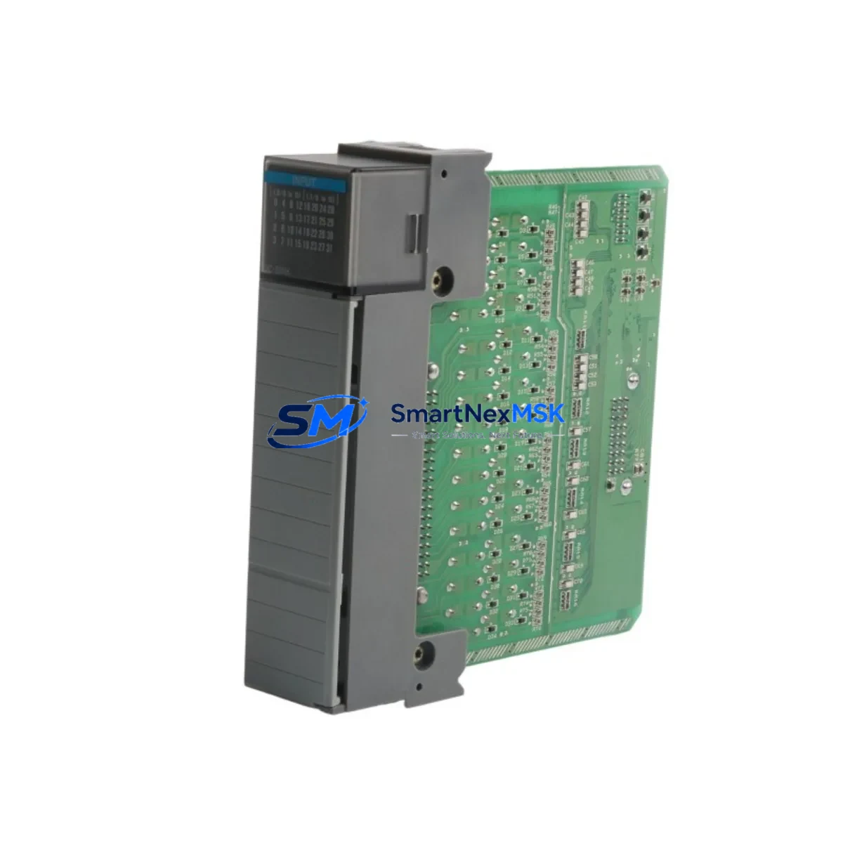
Allen-Bradley 1746-OW4 Maintenance-Ready Spare for SLC 500 Automation
The Allen-Bradley 1746-OW4 is a 4-channel relay output module designed for the SLC 500 modular I/O platform. As a critical discrete output component in relay-based control circuits, it directly governs the switching of field devices including motor starters, solenoid valves, pilot lights, and alarm circuits. When this module fails or degrades, the downstream impact is immediate: unplanned downtime, loss of process control, and potential safety incidents. Maintaining a verified, original spare of the 1746-OW4 in your parts inventory is a foundational element of any responsible maintenance strategy for SLC 500-based automation systems.
This listing supplies an original Allen-Bradley 1746-OW4 relay output module, sourced through verified industrial channels, pre-tested before shipment, and backed by a 12-month warranty. It is suitable for direct replacement in SLC 5/01, 5/02, 5/03, 5/04, and 5/05 processor-based systems using the 1746 I/O chassis.
Spare Maintenance Table
| Parameter | Specification |
|---|---|
| Part Number / SKU | 1746-OW4 |
| Brand | Allen-Bradley (Rockwell Automation) |
| Series | SLC 500 (1746 I/O) |
| Module Type | Relay Output Module |
| Output Channels | 4 (isolated relay contacts) |
| Output Voltage Range | 5–265V AC / 5–125V DC |
| Max Output Current | 2A per point (resistive load) |
| Backplane Current Draw | 75 mA @ 5V DC |
| Isolation | Channel-to-channel and channel-to-backplane isolated |
| Compatible Chassis | 1746-A4, 1746-A7, 1746-A10, 1746-A13 |
| Compatible Processors | SLC 5/01, 5/02, 5/03, 5/04, 5/05 |
| Operating Temperature | 0°C to 60°C (32°F to 140°F) |
| Relative Humidity | 5–95% non-condensing |
| Mounting | 1746 I/O chassis slot (any I/O slot) |
| Origin | USA (Allen-Bradley / Rockwell Automation) |
| Condition | Original, tested before shipment |
| Warranty | 12 Months |
| Shipping | Global express, ESD-safe packaging |
Maintenance Planning for Continuous Operation
Replacing the 1746-OW4 in a live SLC 500 panel is rarely an isolated task. Maintenance engineers and procurement teams should treat this replacement as an opportunity to audit the surrounding control circuit for wear, drift, or latent faults. A structured inspection during the replacement window significantly reduces the risk of repeat downtime.
Begin with the 1746-P2 or 1746-P4 power supply module — verify output voltage stability under load before re-energizing the chassis. A degraded power supply is a common root cause of intermittent I/O faults that are misdiagnosed as module failures. Next, inspect the 1746-IB16 or 1746-IA16 input modules in the same chassis: relay output faults are often preceded by input signal anomalies that go undetected until a field device fails to respond.
Check the terminal blocks and wiring harnesses connected to the 1746-OW4 output terminals. Relay output modules are subject to arcing and contact wear over time; corroded or loose terminals can cause intermittent switching failures that mimic module faults. If the system uses a 1746-BAS or 1746-HSTP1 specialty module in the same chassis, confirm that the chassis backplane connectors are clean and fully seated after the swap.
For systems with communication requirements, verify the 1747-SDN DeviceNet Scanner or 1747-KE DH-485/RS-232 Interface module status after power cycling — communication modules can lose configuration parameters during unplanned shutdowns. If the panel includes a PanelView 550 or PanelView 600 HMI connected via DH-485, confirm that the HMI communication link is restored and tag mappings are intact after the module replacement.
Finally, review the 1492-IFM interface modules or pre-wired terminal assemblies connected to the output field wiring. These passive components are often overlooked during spare parts planning but are critical to signal integrity and safe isolation. Keeping a small buffer stock of 1746-OW4 modules alongside compatible input modules, power supplies, and communication interfaces ensures that your SLC 500 system can be restored to full operation within a single maintenance shift.
Site Replacement Workflow
Step 1 — Verify compatibility before removal. Confirm the replacement 1746-OW4 matches the existing module’s catalog number and firmware revision if applicable. Check the chassis slot assignment in the SLC 500 processor’s I/O configuration (RSLogix 500 or RSLogix Classic) to ensure the output map addresses are preserved.
Step 2 — Safe de-energization. Follow your site LOTO (Lockout/Tagout) procedure. De-energize the 1746 chassis and disconnect field wiring from the output terminal block. Label all wires before removal to prevent miswiring during reinstallation.
Step 3 — Module extraction and inspection. Remove the faulty 1746-OW4 by releasing the top and bottom locking tabs. Inspect the backplane connector for bent pins or contamination. Clean with dry compressed air if necessary before inserting the replacement module.
Step 4 — Reinstallation and wiring. Seat the new 1746-OW4 firmly into the chassis slot until both locking tabs engage. Reconnect field wiring per the original labeling. Torque terminal screws to specification to ensure reliable contact.
Step 5 — Power-up and functional test. Re-energize the chassis and monitor the processor status indicators. Use RSLogix 500 to force each output point ON/OFF and verify field device response. Confirm no fault codes are present in the processor fault table before returning the system to automatic operation.
This workflow minimizes downtime, preserves system compatibility, and ensures the replacement module is fully validated before production resumes. All 1746-OW4 units supplied by SMARTNEXMSK are tested prior to shipment to reduce the risk of DOA (dead-on-arrival) failures in the field.
Spare Parts Support FAQ
Q1: Is this 1746-OW4 an original Allen-Bradley module or a compatible replacement?
This is an original Allen-Bradley 1746-OW4 module sourced through verified industrial supply channels. It is not a third-party compatible or counterfeit substitute. Each unit is inspected and tested before shipment to confirm electrical functionality and physical integrity.
Q2: What is the warranty coverage and what does it include?
All 1746-OW4 modules carry a 12-month warranty from the date of shipment. The warranty covers manufacturing defects and functional failures under normal operating conditions. It does not cover damage caused by incorrect installation, overvoltage, or physical mishandling. Warranty claims are supported with replacement or refund at SMARTNEXMSK’s discretion.
Q3: Can this module replace an older revision of the 1746-OW4 in my existing SLC 500 system?
In most cases, yes. The 1746-OW4 has maintained backward compatibility across revisions within the SLC 500 platform. However, we recommend verifying the chassis type, slot configuration, and RSLogix 500 I/O tree before installation. If you require a specific hardware revision, please contact our technical team with your system details before ordering.
Q4: How quickly can this module be shipped, and do you support emergency procurement?
Standard orders are processed and shipped within 1–2 business days. For emergency downtime situations, please contact us directly at [email protected] or +86 18259474341 to arrange priority handling and expedited freight. We maintain buffer stock of high-demand SLC 500 modules to support urgent replacement needs.
© 2026 SMARTNEXMSK. All rights reserved.
Original Source: https://smartnexmsk.com
Contact: [email protected] | +86 18259474341



