
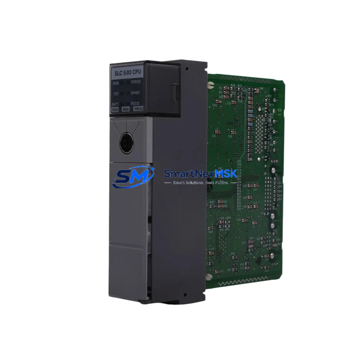
Allen-Bradley 1747-L543 Retrofit-Ready Processor for SLC 5/04 Control Systems
The Allen-Bradley 1747-L543 is a high-performance SLC 5/04 processor module designed for seamless integration into existing SLC 500 control architectures. With 64K of user memory, native Data Highway Plus (DH+) communication, and full compatibility with the 1746 I/O chassis backplane, this processor is the definitive retrofit-ready replacement for aging or discontinued SLC 5/03 and SLC 5/02 processors. Whether you are modernizing a legacy production line, recovering from an unplanned processor failure, or executing a planned control cabinet upgrade, the 1747-L543 delivers the performance and compatibility your system demands — with a 12-month warranty and pre-shipment functional testing included.
Industrial facilities running SLC 500 platforms frequently encounter the challenge of sourcing reliable replacement processors as original units reach end-of-life. The 1747-L543 addresses this directly: it installs into any standard 1746 modular chassis — including the 1746-A4, 1746-A7, 1746-A10, and 1746-A13 rack configurations — without chassis modification. The processor communicates natively over DH+ networks at 57.6K, 115.2K, or 230.4K baud, and its Channel 0 RS-232 port supports DF1 full-duplex and half-duplex protocols for legacy HMI and SCADA connectivity.
Upgrade Compatibility Table
| Parameter | 1747-L543 (SLC 5/04) | Replaces: 1747-L532 (SLC 5/03) | Notes |
|---|---|---|---|
| User Memory | 64K words | 16K / 32K words | Expanded capacity; no program truncation required |
| Backplane Interface | 1746 SLC 500 backplane | 1746 SLC 500 backplane | Direct drop-in; no chassis modification |
| Communication Port 1 | DH+ (Channel 1) | DH+ (Channel 1) | Full network compatibility; retain existing node address |
| Communication Port 0 | RS-232 DF1 / ASCII | RS-232 DF1 / ASCII | HMI and SCADA links preserved without reconfiguration |
| I/O Addressing | Up to 4096 I/O points | Up to 4096 I/O points | Existing 1746-IB16, 1746-OB16, 1746-NI4 addressing retained |
| Programming Software | RSLogix 500 / RSLogix Micro | RSLogix 500 / RSLogix Micro | Existing .RSS project files upload without modification |
| Installation | Slot 0, 1746 chassis | Slot 0, 1746 chassis | Power down chassis before swapping; verify 1746-P4 PSU capacity |
| Retrofit Recommendation | Direct replacement recommended | Verify DH+ node address and baud rate match prior to power-up | |
| Commissioning Focus | Upload program, verify I/O map, test comms | Use RSLinx Classic for DH+ driver configuration | |
| Warranty | 12-Month Warranty | Functional test report available on request | |
Retrofit Planning for Existing Automation Systems
A successful 1747-L543 retrofit begins well before the module arrives on-site. The first step is a thorough audit of the existing control cabinet. Verify that the installed 1746-P4 or 1746-P7 power supply can support the current draw of the 1747-L543 alongside all installed I/O modules — including analog input cards such as the 1746-NI4 or 1746-NI8, digital output modules like the 1746-OB32, and any specialty modules such as the 1746-HSCE high-speed counter or 1746-QS stepper controller. Insufficient power supply headroom is one of the most common causes of intermittent faults after a processor swap.
Next, document the existing DH+ network topology. Record the node address currently assigned to the processor being replaced — this address must be replicated exactly on the 1747-L543 to avoid disrupting communications with upstream SCADA systems, remote I/O adapters, or peer SLC 500 controllers on the same DH+ segment. If the network also includes a 1785-KA5 or 1784-KTX communication interface card connecting to a legacy PLC-5 platform, confirm that the DH+ baud rate is consistent across all nodes before energizing the replacement processor.
Terminal wiring on the 1746 I/O modules does not require modification during a processor swap, as the 1747-L543 uses the same backplane addressing scheme as its predecessors. However, if the retrofit is being combined with an I/O expansion — for example, adding a 1746-IA16 AC input module or a 1746-OW16 relay output module to an existing 1746-A10 chassis — update the I/O configuration in RSLogix 500 before downloading the revised program. Failure to do so will result in an I/O configuration mismatch fault at startup.
For facilities that also operate Panel View terminals — such as the PanelView 550 or PanelView 1000 connected via DH+ — verify that the HMI application’s processor node address and data file references match the 1747-L543 configuration. In most cases, no HMI screen modifications are required when performing a like-for-like processor replacement, but a full screen-by-screen functional test is recommended as part of the commissioning checklist.
If the retrofit scope includes migrating communication from a legacy DH+ backbone to Ethernet/IP, consider pairing the 1747-L543 with a 1761-NET-ENI Ethernet interface module. This allows the SLC 5/04 processor to participate in an EtherNet/IP network while retaining the existing ladder logic program, eliminating the need for a full platform migration to ControlLogix or CompactLogix at this stage.
Downtime Control During System Migration
Minimizing unplanned downtime is the primary operational concern during any SLC 500 processor replacement. The recommended approach is to perform a full program backup from the existing processor using RSLogix 500 before any hardware is disturbed. Save the .RSS project file to at least two separate storage locations and document the current processor status file — including timer accumulated values, counter presets, and any retentive data that must be preserved across the power cycle.
Once the 1747-L543 is installed in Slot 0 of the 1746 chassis, power up the system without placing the processor in Run mode. Use RSLinx Classic to establish a DH+ or RS-232 driver connection and verify that the processor is recognized before downloading the program. After download, perform a controlled I/O force test on critical output channels to confirm that the backplane communication between the processor and all installed 1746 I/O modules is functioning correctly. Only then should the processor be placed in Run mode and the system returned to production.
For facilities where continuous operation is critical, a parallel commissioning strategy is advisable: install and configure the 1747-L543 in a bench test environment using a spare 1746-A4 chassis and a representative set of I/O modules before the scheduled maintenance window. This allows the engineering team to validate program execution, communication links, and HMI connectivity without time pressure, reducing the on-site cutover to a straightforward module swap and program download. Combined with pre-shipment functional testing and the included 12-month warranty, this approach provides the highest level of confidence in a successful, low-downtime retrofit.
Retrofit Support FAQ
Q1: Is the 1747-L543 a direct drop-in replacement for the 1747-L532 (SLC 5/03)?
Yes. The 1747-L543 installs in the same Slot 0 position of any 1746 modular chassis and uses the same backplane interface. The existing RSLogix 500 program (.RSS file) can be uploaded directly without modification. The primary difference is expanded user memory (64K vs. 16K/32K), which is fully backward compatible — no program changes are required unless you choose to utilize the additional memory capacity.
Q2: Will my existing DH+ network and HMI connections work without reconfiguration?
In most cases, yes. Set the DH+ node address on the 1747-L543 to match the address of the processor being replaced, and ensure the baud rate matches the rest of the network. RS-232 Channel 0 connections to PanelView terminals or SCADA systems using DF1 protocol will continue to operate without driver or application changes. A communication link test using RSLinx Classic is recommended before returning the system to production.
Q3: What pre-shipment testing is performed on the 1747-L543?
Each unit undergoes a functional power-on test and communication port verification prior to shipment. A test report is available on request. Units are shipped in anti-static packaging with protective slot covers installed. The 12-month warranty covers manufacturing defects and functional failures under normal operating conditions.
Q4: Can the 1747-L543 be used to expand I/O capacity beyond the original system configuration?
Yes. The 1747-L543 supports up to 4096 I/O points across local and remote chassis. If you are expanding the system with additional 1746 I/O modules or adding a remote I/O adapter such as the 1747-ASB, update the I/O configuration in RSLogix 500 to reflect the new module addresses before downloading the revised program. Consult the 1747-L543 installation manual for chassis power budget calculations when adding modules.
© 2026 SMARTNEXMSK. All rights reserved.
Original Source: https://smartnexmsk.com
Contact: [email protected] | +86 18259474341



