
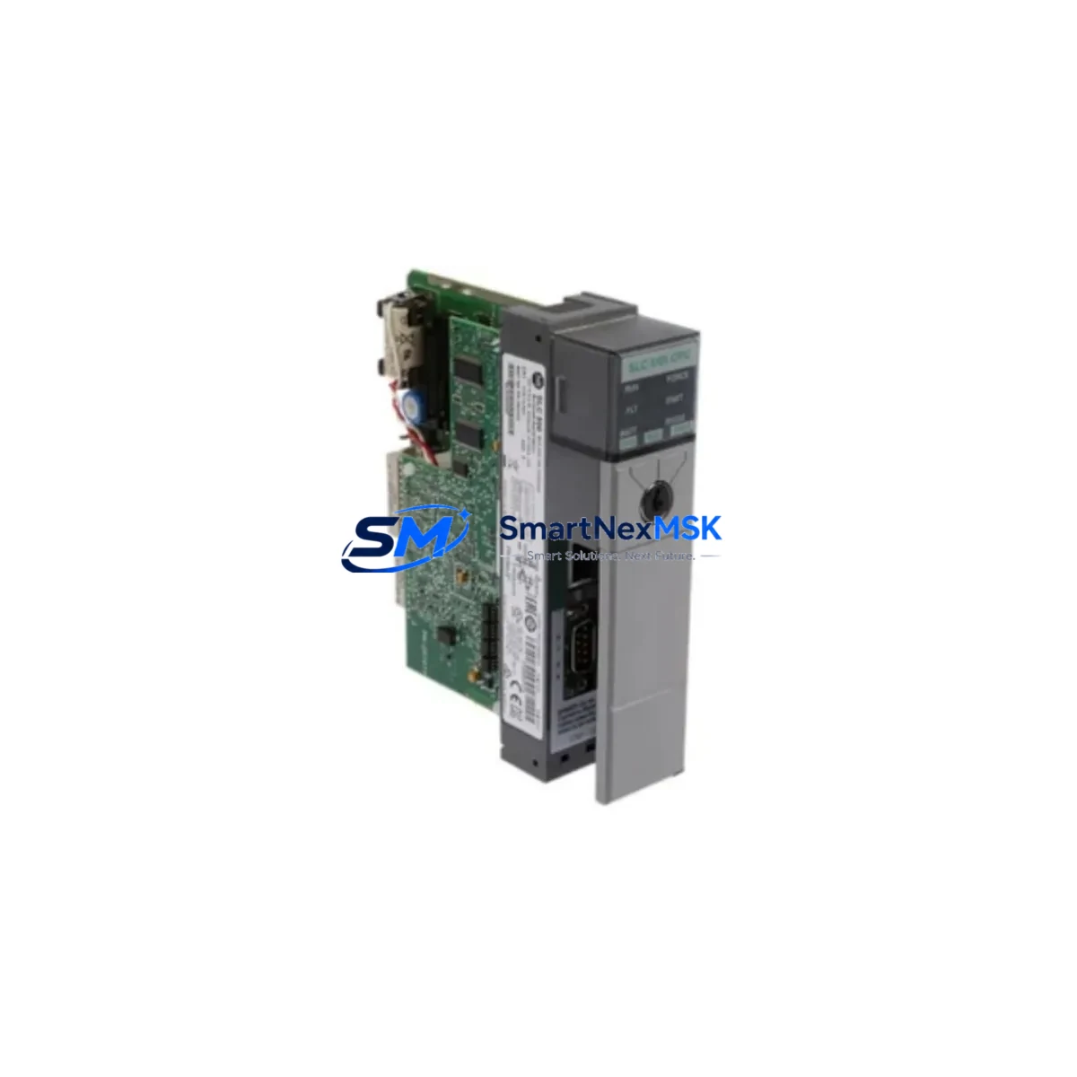
Allen-Bradley 1747-L551/C Maintenance-Ready Spare SLC 500
The Allen-Bradley 1747-L551/C is the SLC 5/05 CPU module with integrated Ethernet/IP communications, designed for the SLC 500 modular chassis platform. As a maintenance-ready original spare, this unit is sourced, inspected, and tested to support rapid replacement in production environments where unplanned downtime carries significant operational and financial risk. Whether you are managing a planned shutdown, responding to an emergency fault, or building out a critical spare inventory for aging SLC 500 infrastructure, the 1747-L551/C provides a direct, firmware-compatible replacement that restores system operation without requiring hardware redesign or re-engineering.
For maintenance engineers and procurement teams responsible for SLC 500-based control systems, having a verified spare of the 1747-L551/C on the shelf is a fundamental risk mitigation strategy. The SLC 5/05 processor communicates natively over Ethernet/IP, enabling integration with SCADA, HMI, and supervisory systems via standard TCP/IP infrastructure. Loss of this CPU module results in complete loss of control for the associated I/O chassis, making rapid replacement capability essential for any facility operating continuous or semi-continuous processes.
Spare Maintenance Table
| Parameter | Specification |
|---|---|
| Part Number | 1747-L551/C |
| Series | SLC 500 / SLC 5/05 |
| Brand | Allen-Bradley (Rockwell Automation) |
| Processor Type | SLC 5/05 CPU with Ethernet/IP |
| Communication Port | Ethernet/IP (10/100 Mbps), RS-232 (DH-485 / DF1) |
| Memory | 64K words user program memory |
| I/O Capacity | Up to 4096 I/O points (modular chassis) |
| Power Supply Compatibility | 1746-P1, 1746-P2, 1746-P4, 1746-P7 |
| Chassis Compatibility | 1746-A4, 1746-A7, 1746-A10, 1746-A13 |
| Operating Temperature | 0°C to 60°C |
| Relative Humidity | 5% to 95% non-condensing |
| Installation | Slot 0, SLC 500 modular chassis |
| Programming Software | RSLogix 500 / Studio 5000 Logix Designer (offline) |
| Condition | Original, tested before shipment |
| Warranty | 12 Months |
| Origin | USA |
Maintenance Planning for Continuous Operation
When replacing the 1747-L551/C in the field, a disciplined maintenance workflow requires more than a simple CPU swap. The SLC 500 control cabinet typically houses a range of interdependent components that should be inspected and verified during the same maintenance window to prevent secondary failures and repeat downtime events.
Begin with the 1746-P2 or 1746-P4 power supply module: a degraded power supply is a leading cause of CPU faults and memory corruption in SLC 500 systems. Measure output voltages under load before reinstalling the replacement CPU. Next, inspect the 1746-IB16 and 1746-OB16 digital I/O modules seated in the chassis — connector corrosion, blown output transistors, or failed input optocouplers can generate persistent fault codes that are incorrectly attributed to the CPU. If the system uses analog signals, verify the 1746-NI4 or 1746-NO4I analog I/O modules for calibration drift and channel integrity.
For systems using DH-485 or RS-232 communications alongside Ethernet/IP, inspect the 1747-AIC Advanced Interface Converter and associated cabling for continuity and termination resistance. If a 1747-SDN DeviceNet Scanner is installed in the chassis, confirm its node address and baud rate settings are preserved in the replacement CPU program file. Panel-mounted PanelView 550 or PanelView 600 HMI terminals communicating via DH-485 should be tested for communication re-establishment after CPU replacement.
At the field wiring level, inspect 1492-W terminal blocks and associated wiring for loose connections, insulation degradation, or overheating evidence — these are common contributors to intermittent I/O faults in older SLC 500 installations. Check signal isolators on 4–20 mA analog loops for correct output range and isolation integrity. Finally, verify that panel fuses and circuit breakers protecting the 24 VDC control power rail are within rated capacity and show no signs of thermal stress.
Maintaining a documented spare parts list that includes the 1747-L551/C alongside these associated components ensures that your maintenance team can execute a complete cabinet restoration within a single planned or emergency maintenance window, minimizing mean time to repair (MTTR) and reducing the risk of cascading failures.
Site Replacement Workflow
Replacing the 1747-L551/C follows a structured procedure to ensure system compatibility and minimize restart time:
- Backup the existing program: Before removing the faulty CPU, use RSLogix 500 to upload and save the current program file, including data files, force tables, and communication configuration. If the CPU is non-responsive, retrieve the backup from your site documentation or SCADA historian.
- Record Ethernet configuration: Note the IP address, subnet mask, gateway, and node name configured on the existing unit. The 1747-L551/C uses BOOTP or static IP assignment — confirm your network infrastructure settings before powering the replacement unit.
- Power down the chassis: De-energize the 1746-P2/P4 power supply via the panel disconnect. Verify zero-energy state with a multimeter before handling the CPU module.
- Seat the replacement module: Install the 1747-L551/C in Slot 0 of the SLC 500 chassis. Ensure the module is fully engaged and the locking tab is secured.
- Download the program: Connect via Ethernet or RS-232, download the saved program file using RSLogix 500, and verify the program checksum matches the backup.
- Restore Ethernet parameters: Configure the IP address and network settings to match the original unit. Test Ethernet/IP connectivity to the SCADA or HMI system before enabling outputs.
- Controlled restart: Power up the chassis, confirm no fault indicators, and perform a controlled I/O test before returning the system to automatic operation.
This workflow supports direct replacement of older SLC 5/05 revisions including the 1747-L551, 1747-L552, and 1747-L553 variants, subject to firmware and memory capacity compatibility verification. The 1747-L551/C is a proven long-term supply item for facilities committed to extending the operational life of SLC 500 infrastructure without migrating to ControlLogix or CompactLogix platforms.
Spare Parts Support FAQ
Q1: What is the shelf life and storage recommendation for the 1747-L551/C spare?
The 1747-L551/C can be stored for extended periods when kept in anti-static packaging in a dry, temperature-controlled environment (10°C–30°C, <70% RH). Battery-backed memory modules should have the battery inspected annually. We recommend rotating spare inventory every 3–5 years and performing a bench power-up test before long-term storage units are deployed to production.
Q2: How is compatibility verified before shipment?
Each 1747-L551/C unit undergoes a pre-shipment functional test including power-on self-test (POST) verification, Ethernet port connectivity check, and firmware revision confirmation. The firmware revision is documented on the shipping label and test report accompanying each unit, allowing your engineering team to confirm compatibility with your existing RSLogix 500 program before installation.
Q3: Can the 1747-L551/C replace earlier SLC 5/05 revisions such as the 1747-L551 Series A or B?
In most applications, yes. The /C revision is backward-compatible with earlier SLC 5/05 hardware revisions at the chassis and I/O level. However, program files created on earlier firmware versions should be verified in RSLogix 500 for any instruction set or data file compatibility flags before downloading to the /C revision. We recommend a bench test with the actual program file prior to live deployment.
Q4: What does the 12-month warranty cover?
The 12-month warranty covers hardware defects and functional failures under normal operating conditions from the date of shipment. It includes free replacement or repair of the defective unit. The warranty does not cover damage resulting from incorrect installation, overvoltage events, physical impact, or unauthorized modification. Our technical support team is available to assist with failure analysis and RMA processing throughout the warranty period.
© 2026 SMARTNEXMSK. All rights reserved.
Original Source: https://smartnexmsk.com
Contact: [email protected] | +86 18259474341



