
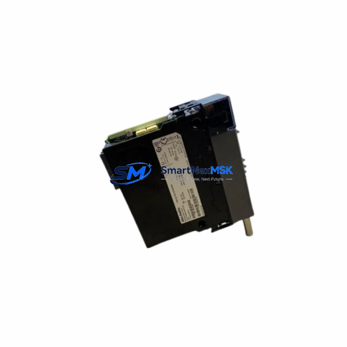
Allen-Bradley 1756-CN2RXT Retrofit-Ready ControlNet Bridge for ControlLogix XT Control Systems
The Allen-Bradley 1756-CN2RXT is a ControlNet redundant media bridge module engineered for the ControlLogix XT (extreme environment) platform. As legacy ControlNet infrastructure ages and original equipment reaches end-of-life, the 1756-CN2RXT has become a critical retrofit component for industrial facilities managing aging control architectures across oil & gas, mining, water treatment, and heavy manufacturing sectors. This module supports redundant ControlNet media, enabling fault-tolerant communication between ControlLogix XT chassis and field devices without requiring a full system redesign.
For engineers and procurement teams sourcing this module as a direct replacement for a failed or discontinued unit, the 1756-CN2RXT slots into the 1756 XT-rated chassis backplane and communicates natively with the ControlLogix L7x and L8x series controllers. Before installation, technicians must verify the chassis power supply capacity — the 1756-PA75R or 1756-PB75R power supply modules are commonly paired in XT configurations and must provide sufficient backplane current budget when adding or replacing communication modules. Confirm the module’s slot address assignment in RSLogix 5000 or Studio 5000 Logix Designer matches the original configuration to avoid I/O tree remapping.
Upgrade Compatibility Table
| Parameter | Detail |
|---|---|
| Module SKU | 1756-CN2RXT |
| Series | ControlLogix XT (Series B) |
| Backplane Interface | 1756 XT-rated backplane (1756-A4LXT, 1756-A7LXT, 1756-A13LXT) |
| Communication Protocol | ControlNet (redundant coaxial media) |
| Replaces / Compatible With | 1756-CN2R (standard), 1756-CN2 (single media, non-XT) |
| Controller Compatibility | 1756-L71, 1756-L72, 1756-L73, 1756-L74, 1756-L75, 1756-L81E, 1756-L82E, 1756-L83E, 1756-L84E, 1756-L85E |
| Installation Requirement | XT-rated chassis; confirm backplane current budget with installed power supply |
| Firmware Compatibility | Compatible with RSLogix 5000 v20+ and Studio 5000 Logix Designer v21+ |
| Commissioning Tool | RSNetWorx for ControlNet (required for network scheduling) |
| Debugging Focus | Module slot address, NUT (Network Update Time), scheduled vs. unscheduled connections |
| Warranty | 12 Months — covers hardware defects, DOA replacement, and functional verification |
Retrofit Planning for Existing Automation Systems
Replacing the 1756-CN2RXT in an operating plant requires a structured approach to avoid unplanned downtime and program loss. Begin by documenting the existing ControlNet network topology using RSNetWorx for ControlNet — export the current network schedule (NUT and connection list) before any hardware is disturbed. This schedule file is essential for re-commissioning after the module swap.
In a typical ControlLogix XT retrofit scenario, the 1756-CN2RXT occupies a dedicated slot in an XT chassis such as the 1756-A7LXT or 1756-A13LXT. Adjacent slots may house the 1756-L73XT or 1756-L75XT controller, 1756-EN2TXT Ethernet/IP bridge modules for supervisory SCADA connectivity, and analog or digital I/O modules such as the 1756-IF16 or 1756-OB16E. When replacing the ControlNet bridge, confirm that none of these adjacent modules are affected by backplane power redistribution — use the chassis power budget calculator available in the Rockwell Automation product selection toolbox.
Terminal wiring on the ControlNet side uses BNC connectors for coaxial cable. Inspect both the A and B media connectors for corrosion or mechanical damage before re-terminating. In redundant media configurations, both coaxial runs must be intact and properly terminated with 75-ohm terminators at each end of the trunk. Failure to terminate correctly will cause media faults and degrade network reliability even if the module itself is functional.
For facilities migrating from an older 1756-CN2 (single media, non-XT) to the 1756-CN2RXT, the module address in the I/O tree must be preserved. Export the controller project from Studio 5000 Logix Designer before the swap, verify the module definition matches the new hardware revision, and update the module properties if the Series designation has changed from A to B. HMI screens built in FactoryTalk View SE or FactoryTalk View ME that reference ControlNet device tags should be validated after the swap to confirm tag paths remain intact — particularly for any displays that read diagnostic status bits from the bridge module itself.
In multi-chassis architectures where the 1756-CN2RXT bridges ControlNet between a local chassis and a remote chassis housing 1756-IB32 digital input modules or 1756-OF8 analog output modules, verify that the remote chassis power supply — typically a 1756-PA75R — is within its current budget after the module replacement. Remote I/O chassis that have been in service for extended periods may have accumulated additional modules since the original commissioning, and the power budget may be tighter than the original design documents indicate.
Programming cable access during retrofit is typically via the 1756-USB or 1784-U2DHP USB-to-DH+ adapter for legacy program recovery tasks. If the original program backup is unavailable, a live upload from the controller via Ethernet using the 1756-EN2TXT is the preferred method before any hardware changes are made.
Downtime Control During System Migration
Minimizing production interruption during a ControlNet bridge replacement requires pre-staging the replacement 1756-CN2RXT module and verifying its firmware revision matches the existing network configuration before the maintenance window begins. Confirm the module is functional using a bench test chassis if available — power the module, connect it to a laptop running RSNetWorx for ControlNet, and verify it enumerates correctly on a test network segment.
During the actual swap, place the controller in Program mode before removing the failed module. This prevents the controller from generating major faults due to lost ControlNet connections. In redundant controller configurations using the 1756-RM2 redundancy module, initiate a manual switchover to the secondary chassis before beginning work on the primary chassis to maintain process continuity. After installing the replacement 1756-CN2RXT, restore the saved network schedule using RSNetWorx for ControlNet, verify all scheduled and unscheduled connections are re-established, and confirm I/O data is updating correctly in the controller tag database before returning the system to Run mode.
Keep the original failed module on-site until the replacement has been in stable operation for at least 72 hours. This provides a fallback reference for any unexpected behavior and allows the maintenance team to compare hardware revision labels if discrepancies arise during commissioning. All retrofit activities should be logged in the plant’s maintenance management system with before/after photos of terminal connections and module slot positions.
Retrofit Support FAQ
Q: Is the 1756-CN2RXT a direct drop-in replacement for the 1756-CN2R?
A: The 1756-CN2RXT is the XT (extreme environment) rated variant of the 1756-CN2R. It is physically and functionally compatible with XT-rated 1756 chassis. If your existing chassis is a standard (non-XT) 1756 chassis, the standard 1756-CN2R is the appropriate replacement. Confirm your chassis part number before ordering.
Q: Do I need to reschedule the ControlNet network after replacing this module?
A: Yes. ControlNet is a scheduled network, and any change to network hardware — including a module replacement — requires re-running RSNetWorx for ControlNet to verify and re-download the network schedule. Failure to reschedule can result in connection timeouts and controller faults. Always export the existing schedule before the swap and re-import it after the replacement module is installed.
Q: What wiring checks are required before powering up the replacement module?
A: Inspect both BNC coaxial connectors (Media A and Media B) for secure seating and verify 75-ohm termination at both ends of each trunk segment. Check that the module is fully seated in the backplane slot and the locking tab is engaged. Confirm the chassis power supply current budget accommodates the module’s backplane current draw before applying power.
Q: What does the 12-month warranty cover?
A: All units are shipped after functional verification testing. The 12-month warranty covers hardware defects and DOA (dead on arrival) failures. In the event of a warranty claim, contact [email protected] with your order reference and a description of the fault. Replacement or refund will be processed within the warranty period from the date of shipment.
© 2026 SMARTNEXMSK. All rights reserved.
Original Source: https://smartnexmsk.com
Contact: [email protected] | +86 18259474341



