
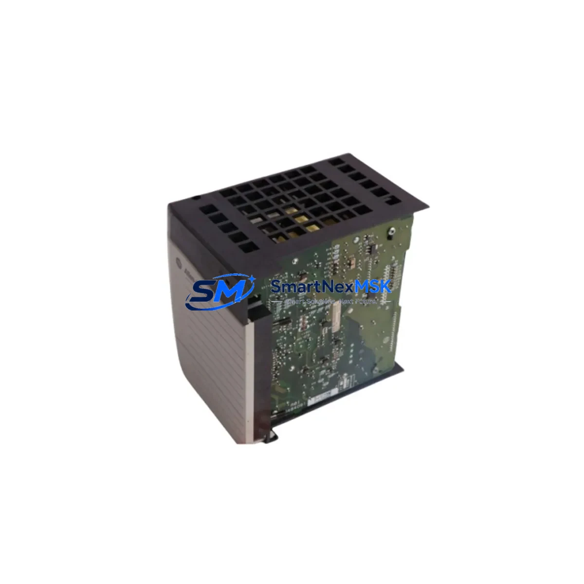
Allen-Bradley 1756-IF4XOF2F Retrofit-Ready Analog I/O for ControlLogix Systems
The Allen-Bradley 1756-IF4XOF2F is a high-density analog combination I/O module designed for the ControlLogix 1756 chassis platform. Featuring four isolated analog input channels and two analog output channels in a single backplane slot, this module is a proven solution for legacy system modernization, discontinued spare replacement, and control cabinet upgrades across process, discrete, and hybrid automation environments. Whether you are replacing a failed unit on a running line or executing a planned retrofit of an aging DCS or PLC system, the 1756-IF4XOF2F delivers the signal fidelity, backplane bandwidth, and Logix-native tag integration required for seamless migration.
This module supports both voltage (±10 V) and current (0–20 mA / 4–20 mA) signal ranges on all input channels, with selectable range per channel via RSLogix 5000 or Studio 5000 Logix Designer. The two output channels support 0–20 mA and ±10 V simultaneously, making it particularly well-suited for valve positioner control, variable frequency drive (VFD) speed reference, and PID loop feedback in legacy retrofit projects. The module communicates over the ControlLogix backplane via the 1756 chassis, and its configuration is stored in the controller project file, eliminating the need for DIP switches or manual hardware configuration during replacement.
When planning a retrofit around the 1756-IF4XOF2F, engineers must verify several critical compatibility parameters before commissioning. First, confirm the power budget of the 1756-PA75 or 1756-PB75 power supply currently installed in the chassis — the 1756-IF4XOF2F draws backplane current from the 1756 chassis and must be accounted for alongside co-resident modules such as the 1756-L73 or 1756-L74 ControlLogix controller, 1756-EN2T Ethernet/IP communication module, and any 1756-OB16I or 1756-IB16 digital I/O modules sharing the same rack. Exceeding the chassis power budget is a common oversight during slot-for-slot replacements.
Upgrade Compatibility Table
| Parameter | Detail |
|---|---|
| Module SKU | 1756-IF4XOF2F |
| Platform | Allen-Bradley ControlLogix 1756 Series |
| Analog Inputs | 4 channels, isolated, ±10 V / 0–20 mA / 4–20 mA selectable |
| Analog Outputs | 2 channels, ±10 V and 0–20 mA simultaneous |
| Backplane Interface | 1756 ControlLogix chassis (any slot) |
| Compatible Chassis | 1756-A4, 1756-A7, 1756-A10, 1756-A13, 1756-A17 |
| Compatible Controllers | 1756-L61, 1756-L62, 1756-L63, 1756-L71, 1756-L72, 1756-L73, 1756-L74, 1756-L83E |
| Programming Software | RSLogix 5000 v16+, Studio 5000 Logix Designer v21+ |
| Communication Protocol | ControlLogix Backplane (proprietary), EtherNet/IP via controller |
| Common Replacement For | 1756-IF4XOF2F (same SKU, discontinued batch), 1756-IF6I, 1756-OF4 |
| Installation Requirement | Slot-based, no DIP switch; configure via controller project file |
| Firmware Compatibility | Module firmware auto-updated by controller on first scan |
| Warranty | 12 Months — covers hardware defects, DOA replacement, and functional verification |
Retrofit Planning for Existing Automation Systems
A successful retrofit using the 1756-IF4XOF2F begins well before the module arrives on site. Start by auditing the existing 1756 chassis layout: document every occupied slot, the module catalog number, the I/O tree address in the controller project, and the terminal wiring on each module’s removable terminal block (RTB). The 1756-IF4XOF2F uses a 1756-TBCH or 1756-TBS6H RTB — confirm which style is currently installed and order a matching spare RTB to allow pre-wiring before the maintenance window opens.
Next, review the controller program in Studio 5000 Logix Designer. The 1756-IF4XOF2F appears in the I/O tree as a local or remote module with a defined slot address. If you are replacing a failed module of the same catalog number, the slot address and tag database remain intact — no program changes are required. If you are migrating from a different analog module such as the 1756-IF6I (6-channel voltage input) or the 1756-OF4 (4-channel analog output), you will need to remap tag references in the ladder logic or function block diagrams, update the module definition in the I/O tree, and verify that all PID instruction input/output references resolve correctly after the change.
For systems that include a 1756-EN2T or 1756-EN2TR EtherNet/IP bridge module connecting remote 1756 chassis over a ring topology, confirm that the communication path to the remote rack remains intact during the swap. If the 1756-IF4XOF2F is installed in a remote chassis connected via a 1756-CNB or 1756-CNBR ControlNet bridge, verify that the ControlNet network schedule is not disrupted — unscheduled messaging will continue, but scheduled I/O connections may require a network reschedule after module replacement.
Terminal wiring on the 1756-IF4XOF2F follows a standard screw-terminal RTB layout. Each input channel uses a differential pair (IN+ / IN−) with a shield terminal, and each output channel uses a single-ended pair (OUT / COM). Before powering up, verify signal source impedance on all input channels — the module’s input impedance is greater than 1 MΩ for voltage mode and approximately 250 Ω for current mode. Mismatched wiring from a previous 1756-IF6I installation (which uses a different terminal assignment) is a common source of commissioning errors and must be corrected before enabling the module in the controller.
If the retrofit involves upgrading from a legacy SLC 500 or PLC-5 platform to ControlLogix, the 1756-IF4XOF2F is typically introduced alongside a 1756-DHRIO or 1756-DNB gateway module to bridge legacy Data Highway Plus or DeviceNet field devices into the new Logix environment. In these cross-platform migrations, the analog signal wiring is often reused directly, but the controller program must be converted using the RSLogix Project Migrator tool, and all analog scaling routines must be re-verified against the new module’s resolution (16-bit, ±32,767 counts) versus the legacy module’s 12-bit or 13-bit resolution.
Downtime Control During System Migration
Minimizing unplanned downtime during a 1756-IF4XOF2F replacement requires a structured pre-outage preparation protocol. Before the maintenance window, export the current controller project from Studio 5000 and save a timestamped backup to a secure location — never perform a module swap on a controller running a project that has not been backed up. If the system supports redundancy via a 1756-RM2 or 1756-RM2XT redundancy module, confirm that the secondary chassis is synchronized and that a controlled switchover can be initiated before the primary chassis is taken offline.
For non-redundant systems, coordinate with the process team to place all PID loops in manual mode before removing the module. This prevents integrator windup and output bumps when the analog signals drop during the swap. Document the current output values on the 1756-IF4XOF2F’s two output channels so that operators can manually hold the downstream actuators — valve positioners, VFD speed references, or current-to-pneumatic (I/P) transducers — at their last known good setpoints during the outage window.
Physical module replacement takes less than five minutes: inhibit the module in the I/O tree, remove the RTB, press the module release latch, slide the old module out, insert the replacement 1756-IF4XOF2F, reconnect the RTB, and uninhibit the module. The controller will automatically download the module configuration and begin scanning within two to three seconds. Verify that all channel status indicators on the module faceplate show green before returning PID loops to automatic mode. Total controlled downtime for a prepared swap is typically under 15 minutes.
For systems where even a brief outage is unacceptable, consider using a 1756-A17 chassis with an available spare slot to pre-install and configure the replacement 1756-IF4XOF2F as a shadow module before the swap. This allows the module firmware and configuration to be validated online before the physical replacement occurs, further reducing commissioning risk during the maintenance window.
Retrofit Support FAQ
Q: Is the 1756-IF4XOF2F a direct drop-in replacement for a failed unit of the same catalog number?
A: Yes. If you are replacing a failed 1756-IF4XOF2F with a unit of the same catalog number in the same chassis slot, no program changes are required. The controller will automatically download the stored module configuration on the first scan. Confirm that the RTB wiring is intact and that the module firmware revision is compatible with your controller firmware — firmware mismatches are flagged in the controller’s fault log and can be resolved by updating the module definition in Studio 5000.
Q: Can the 1756-IF4XOF2F replace a 1756-IF6I or 1756-OF4 in an existing system?
A: The 1756-IF4XOF2F is a combination module (4 inputs + 2 outputs) and is not a channel-for-channel replacement for the 1756-IF6I (6 inputs only) or 1756-OF4 (4 outputs only). However, it can serve as a consolidation module in systems where both analog input and output functions are needed in a single slot. Tag remapping and I/O tree reconfiguration in Studio 5000 are required, and terminal wiring must be re-verified against the 1756-IF4XOF2F RTB pinout.
Q: What commissioning checks are required after installing the replacement module?
A: After installation, verify the following: (1) all channel status LEDs on the module faceplate show green; (2) no module fault codes appear in the controller’s I/O fault log; (3) analog input readings match known field signal values within the module’s specified accuracy (±0.1% of full scale); (4) analog output channels drive the correct current or voltage at the field device terminals; (5) all PID loops return to automatic mode without output bumps or integrator windup. Document the commissioning results and retain them with the maintenance record.
Q: What does the 12-month warranty cover, and what is the return process?
A: The 12-month warranty covers hardware defects, dead-on-arrival (DOA) units, and functional failures under normal operating conditions. Each unit shipped by SMARTNEXMSK undergoes pre-shipment functional testing including channel-level signal verification. If a warranty claim is required, contact [email protected] with the order number, module serial number, and a description of the fault. Replacement units are dispatched within 3 business days of claim approval. The warranty does not cover damage caused by incorrect wiring, overvoltage, or installation in an incompatible chassis.
© 2026 SMARTNEXMSK. All rights reserved.
Original Source: https://smartnexmsk.com
Contact: [email protected] | +86 18259474341



