
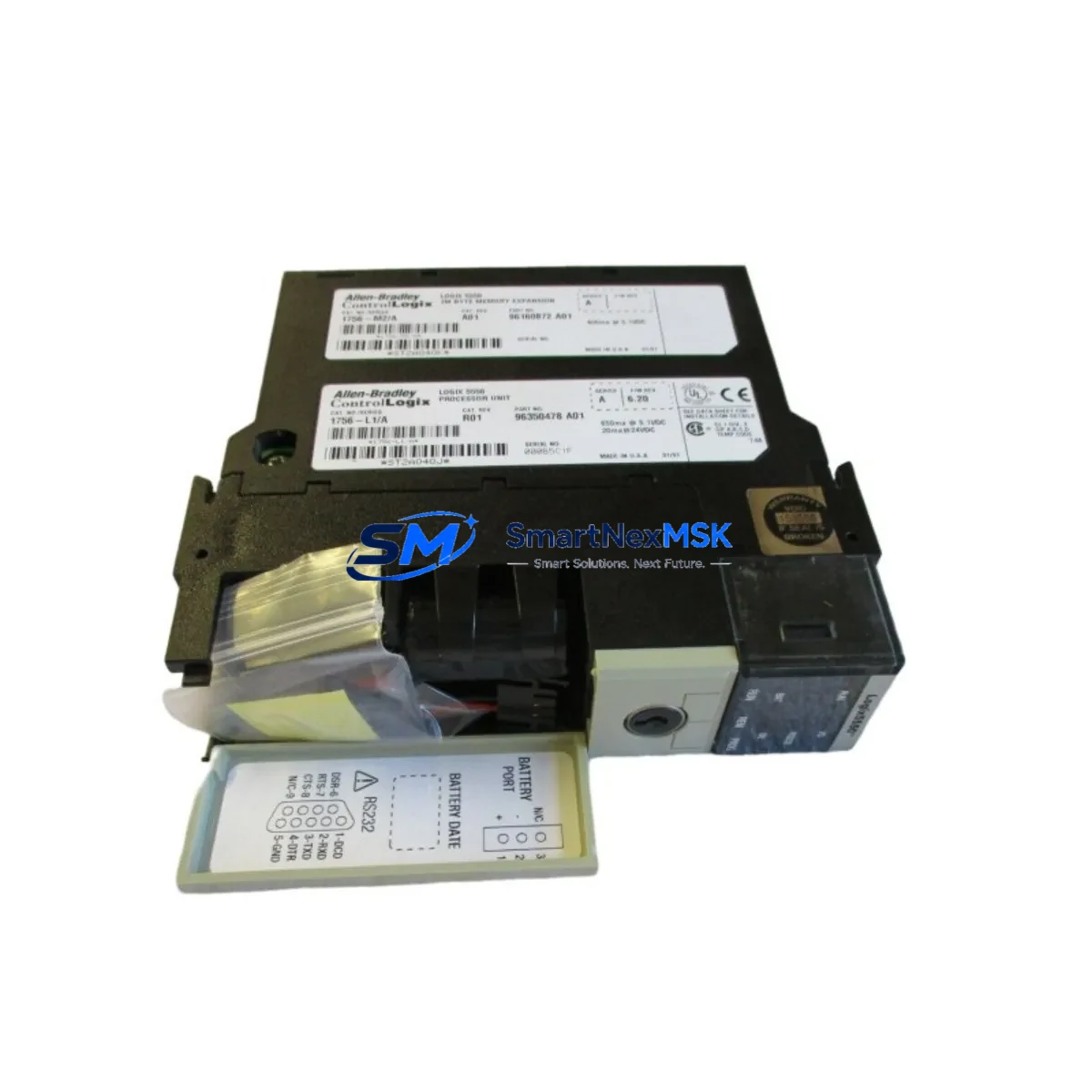
Allen-Bradley 1756-L1M2 Retrofit-Ready Processor for ControlLogix Systems
The Allen-Bradley 1756-L1M2 is a legacy ControlLogix processor that remains a critical component in thousands of active production lines worldwide. As Rockwell Automation has transitioned its controller portfolio toward the 1756-L7x and 1756-L8x series, many facilities operating on the original 1756 Series chassis face the challenge of sourcing reliable, tested replacements for the 1756-L1M2 without triggering a full system overhaul. SMARTNEXMSK maintains verified stock of the 1756-L1M2 to support planned retrofits, emergency replacements, and phased control system upgrades — all backed by a 12-month warranty and pre-shipment functional testing.
Upgrade Compatibility Table
| Parameter | 1756-L1M2 (This Unit) | Upgrade Path / Notes |
|---|---|---|
| Chassis Compatibility | 1756 ControlLogix Chassis (4, 7, 10, 13, 17-slot) | Compatible with all standard 1756-Axxx chassis; verify slot addressing |
| Backplane Interface | ControlLogix standard backplane | Direct drop-in; no backplane adapter required |
| Memory | 512 KB user memory | Upgrade to 1756-L61 or 1756-L71 for expanded memory requirements |
| Communication Protocols | EtherNet/IP via 1756-ENBT or 1756-EN2T bridge modules | Retain existing 1756-ENBT; verify firmware revision compatibility |
| Programming Software | RSLogix 5000 v13–v20 / Studio 5000 Logix Designer | Program files (.ACD) are forward-compatible; verify revision on restore |
| I/O Module Compatibility | All 1756 Series I/O modules (digital, analog, specialty) | 1756-IB16, 1756-OB16E, 1756-IF8 remain fully compatible |
| Power Supply Requirement | 1756-PA72 or 1756-PB72 chassis power supply | Verify power budget; add 1756-PA75R for redundant power if required |
| Installation Method | Hot-swap capable (with proper procedure) | Follow Rockwell Publication 1756-IN001 for safe hot-swap sequence |
| Replacement Recommendation | Direct replacement for failed or end-of-life 1756-L1M2 units | For long-term migration, consider 1756-L71 with 1756-M13 memory card |
| Warranty | 12-Month Warranty — All units tested prior to shipment | |
Retrofit Planning for Existing Automation Systems
Replacing the 1756-L1M2 in a live production environment requires careful pre-planning across multiple system layers. Before the replacement unit arrives on-site, engineers should export and archive the current .ACD program file using RSLogix 5000 or Studio 5000 Logix Designer, and document all I/O module slot assignments within the chassis. In a typical 10-slot 1756-A10 chassis, the processor occupies slot 0, with downstream modules such as the 1756-IB16 digital input module, 1756-OB16E digital output module, and 1756-IF8 analog input module occupying fixed addresses that must be preserved post-swap.
Communication continuity is equally critical. If the control network relies on EtherNet/IP via a 1756-ENBT or 1756-EN2T bridge module, the IP address configuration and connection parameters must be documented before the processor is removed. In systems using DeviceNet or ControlNet, the 1756-DNB or 1756-CNB communication modules must remain powered and undisturbed during the processor swap to avoid network faults cascading to field devices.
For facilities running HMI panels — particularly FactoryTalk View SE stations or PanelView Plus terminals communicating via RSLinx Classic — the tag database and screen logic should be verified against the restored program to confirm that all referenced controller tags remain intact. Any tag renaming or address remapping introduced during the retrofit must be reflected in the HMI project before go-live.
Power budget verification is a frequently overlooked step. The 1756-PA72 chassis power supply supports a defined backplane current budget; adding or replacing modules — including the processor itself — requires recalculating the total draw across all installed 1756 Series modules. If the existing power supply is operating near capacity, a 1756-PA75R redundant power supply module should be considered as part of the retrofit scope.
For systems that include a 1756-RM redundancy module pair, the replacement procedure must account for the primary/secondary controller synchronization sequence. Attempting a processor swap without first disabling redundancy mode can result in an uncontrolled failover. Always place the redundancy pair in maintenance mode via RSLogix 5000 before proceeding.
Finally, if the retrofit involves migrating from an older 1756-L1M2 to a higher-capacity processor such as the 1756-L61 or 1756-L71, a 1747-CP3 or 1756-CP3 programming cable may be required for initial firmware download and configuration, particularly in facilities where network access to the controller is restricted during commissioning.
Downtime Control During System Migration
Minimizing unplanned downtime during a 1756-L1M2 replacement begins with a structured pre-outage checklist. The most effective approach is to schedule the swap during a planned maintenance window, with the replacement processor pre-staged, firmware pre-loaded to the correct revision, and the program file verified on a bench test setup before the production chassis is touched.
To protect original program logic, always maintain at least two independent backups of the .ACD file — one stored locally on the engineering workstation and one archived to a network location or USB drive. If the system uses a 1784-CF64 CompactFlash card for non-volatile program storage, verify that the card is current before removal and use it as the primary restore medium on the replacement unit.
During the physical swap, follow the hot-swap procedure only if the chassis power supply and all I/O modules are confirmed stable. For critical processes where even a brief I/O interruption is unacceptable, a cold-swap with a coordinated process hold is the safer path. After the replacement processor is seated and powered, allow the backplane to re-enumerate all modules before initiating a program download. Confirm that all I/O module status indicators return to normal run state before releasing the process back to automatic control.
Post-swap, conduct a structured loop check across all critical I/O points, verify communication link status on all 1756-ENBT or 1756-EN2T modules, and confirm HMI tag connectivity before signing off on the retrofit. Document the completed swap with before/after photos, firmware revision records, and a signed commissioning checklist to support future maintenance and audit requirements.
Retrofit Support FAQ
Q1: Is the 1756-L1M2 a direct drop-in replacement for a failed unit in an existing ControlLogix chassis?
Yes. The 1756-L1M2 is physically and electrically compatible with all standard 1756 Series chassis. Provided the replacement unit carries the same or compatible firmware revision, the existing program file can be restored directly from a CompactFlash card or via RSLogix 5000 download without hardware modification.
Q2: What firmware revision should I specify when ordering, and how is it verified before shipment?
All units supplied by SMARTNEXMSK are tested and the firmware revision is documented prior to shipment. If your application requires a specific revision for compatibility with RSLogix 5000 or Studio 5000 Logix Designer, please specify this at the time of order. We will confirm the available revision and advise on any upgrade steps required.
Q3: Can the 1756-L1M2 communicate with third-party SCADA systems or non-Rockwell HMI platforms?
Yes, via EtherNet/IP using a 1756-ENBT or 1756-EN2T bridge module. The processor supports standard CIP messaging, which is compatible with most modern SCADA platforms and HMI systems that support EtherNet/IP or OPC-DA/UA via RSLinx Classic or RSLinx Enterprise. Verify the communication driver version on the SCADA host before commissioning.
Q4: What does the 12-month warranty cover, and what is the process if a unit fails after installation?
The 12-month warranty covers functional failure under normal operating conditions. All units undergo pre-shipment functional testing including backplane communication verification, memory integrity check, and firmware confirmation. In the event of a warranty claim, contact [email protected] with the order reference and fault description. Replacement or repair will be coordinated with minimum lead time to reduce production impact.
© 2026 SMARTNEXMSK. All rights reserved.
Original Source: https://smartnexmsk.com
Contact: [email protected] | +86 18259474341



