
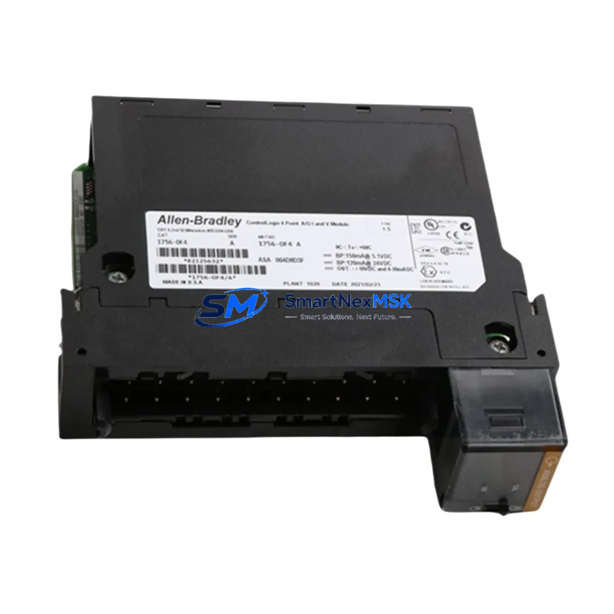
Allen-Bradley 1756-OF4 Retrofit-Ready Analog Output Module for ControlLogix Control Systems
The Allen-Bradley 1756-OF4 is a 4-channel analog output module designed for the ControlLogix 1756 chassis platform. As legacy automation systems approach end-of-life or require capacity expansion, the 1756-OF4 serves as a proven retrofit solution for facilities migrating from older SLC 500, PLC-5, or early ControlLogix configurations. Each unit supplied by SMARTNEXMSK is fully tested, serialized, and backed by a 12-month warranty, ensuring reliable drop-in replacement with minimal disruption to your production environment.
Whether you are upgrading a legacy control cabinet, recovering from an unplanned module failure, or executing a planned system modernization, the 1756-OF4 integrates directly into existing 1756 backplanes without requiring chassis replacement. Its compatibility with the standard ControlLogix 1756-A7, 1756-A10, and 1756-A13 rack families means that field engineers can complete a hot-swap or cold-swap replacement within a single maintenance window.
Upgrade Compatibility Table
| Parameter | Details |
|---|---|
| Module SKU | 1756-OF4 |
| Platform | Allen-Bradley ControlLogix 1756 Series |
| Output Channels | 4 Analog Output (Voltage / Current selectable) |
| Output Range | 0–10 VDC / ±10 VDC / 4–20 mA / 0–20 mA |
| Backplane Interface | 1756 ControlLogix Backplane (standard) |
| Compatible Racks | 1756-A4, 1756-A7, 1756-A10, 1756-A13, 1756-A17 |
| Compatible Controllers | 1756-L61, 1756-L62, 1756-L63, 1756-L71, 1756-L72, 1756-L73, 1756-L74, 1756-L75, 1756-L81, 1756-L82, 1756-L83, 1756-L84, 1756-L85 |
| Communication Protocol | EtherNet/IP via 1756-EN2T / 1756-EN3TR; ControlNet via 1756-CN2 |
| Replacement Candidates | 1756-OF4 (earlier firmware revisions), legacy SLC 500 analog output via migration bridge |
| Installation Requirement | Module key must match slot configuration; RSLogix 5000 / Studio 5000 tag re-mapping required if slot address changes |
| Commissioning Tool | Studio 5000 Logix Designer v21 and above; 1756-CP3 or USB-1761-CBL-PM02 programming cable |
| Warranty | 12 Months — covers hardware defects, tested prior to shipment |
Retrofit Planning for Existing Automation Systems
A successful 1756-OF4 retrofit begins well before the module arrives on-site. Engineers should audit the existing 1756 chassis for available slot positions, confirm that the 1756-PA72 or 1756-PB72 power supply has sufficient current budget to support the additional analog output load, and verify that the backplane keying is set correctly for the OF4 module type. In multi-chassis architectures connected via a 1756-CN2 ControlNet bridge module or a 1756-EN2T EtherNet/IP communication module, the module’s slot address must be pre-configured in the Studio 5000 project tree before physical installation to avoid I/O faulting on the controller.
For facilities transitioning from SLC 500 analog output cards such as the 1746-NO4I or 1746-NO4V, a direct slot-for-slot swap is not possible due to platform differences. In these cases, a migration strategy using a 1756-DHRIO or a 1761-NET-ENI adapter may be required to bridge legacy DH+ or DH-485 networks while the new ControlLogix platform is commissioned in parallel. During this transition period, the 1756-OF4 can be configured in listen-only mode to shadow existing output values before the cutover, reducing the risk of process upsets.
Terminal wiring on the 1756-OF4 uses a removable 20-pin RTB (Removable Terminal Block). When replacing a failed module, the RTB can be transferred directly to the new unit without rewiring field devices — a critical time-saver during emergency replacements. Engineers should confirm that the field wiring gauge is compatible with the RTB’s screw terminal torque specification (0.9 N·m) and that shielded cable is used for all analog signal runs exceeding 3 meters to minimize noise interference from adjacent 1756-IB16 or 1756-OB16E digital I/O modules in the same chassis.
HMI integration should also be validated during the retrofit. If the facility uses a PanelView Plus 7 or PanelView 800 terminal connected via EtherNet/IP, the tag database in FactoryTalk View Studio must be updated to reflect any new module slot assignments. Analog output scaling parameters — including engineering unit ranges and alarm setpoints — should be re-verified against the process P&ID documentation to ensure that the 1756-OF4’s output resolution (16-bit) matches the expectations of downstream field instruments such as control valves, variable frequency drives, or positioners.
For larger system upgrades involving multiple analog output points, consider pairing the 1756-OF4 with the 1756-IF16 (16-channel analog input module) to achieve a balanced I/O architecture within a single 1756-A10 rack. This combination is commonly deployed in process control applications involving PID loops, where both setpoint output and process variable feedback must reside on the same backplane to minimize scan-time latency. The 1756-L73 or 1756-L83 controller is recommended for these configurations due to its expanded memory and task scheduling capacity.
Downtime Control During System Migration
Minimizing unplanned downtime is the primary concern during any analog output module replacement. SMARTNEXMSK recommends a structured three-phase approach: pre-staging, hot-swap execution, and post-swap verification.
Pre-Staging: Before the maintenance window opens, export the existing Studio 5000 project and create a full backup of the controller program, including all AOI (Add-On Instruction) definitions, UDT (User-Defined Data Type) structures, and HMI tag cross-references. Confirm that the 1756-OF4 replacement unit has been bench-tested and that its firmware revision matches or exceeds the revision currently in service. If the existing module is running firmware below v3.x, a firmware upgrade via ControlFLASH or ControlFLASH Plus should be performed on the bench unit prior to installation.
Hot-Swap Execution: The ControlLogix platform supports module removal and insertion under power (RIUP) when the controller is in Run mode, provided the I/O connection is configured as a “Listen Only” or the program logic includes appropriate fault handling rungs. Before removing the failed 1756-OF4, place all affected output channels in a safe state (typically 0 mA or 0 VDC) using the controller’s inhibit function or a manual override at the field device level. Insert the replacement module and allow the controller to re-establish the I/O connection — this typically completes within 3–5 seconds on a healthy EtherNet/IP network.
Post-Swap Verification: After the module reconnects, verify that all four output channels are producing the correct engineering unit values by comparing the controller tag values against the field instrument readings. Check the module’s diagnostic indicators (green RUN LED, no FLT LED) and review the controller’s I/O fault log in Studio 5000. If the RTB was transferred from the failed module, perform a point-to-point continuity check on all 20 terminals before returning the system to automatic control. Document the replacement in the facility’s maintenance management system (CMMS) and retain the 12-month warranty certificate issued with the SMARTNEXMSK shipment.
Retrofit Support FAQ
Q1: Is the SMARTNEXMSK 1756-OF4 a direct drop-in replacement for my existing ControlLogix analog output module?
Yes. The 1756-OF4 supplied by SMARTNEXMSK is a genuine or equivalent-grade module that installs directly into any 1756-series chassis slot previously occupied by a 1756-OF4. No hardware modifications are required. The module’s RTB is transferable, and the Studio 5000 project does not require re-compilation if the slot address remains unchanged.
Q2: What commissioning steps are required after installing the replacement module?
After physical installation, verify that the controller re-establishes the I/O connection (check the RUN LED on the module front face). In Studio 5000, navigate to the I/O tree, right-click the 1756-OF4 entry, and select “Properties” to confirm the connection status shows “Running.” Perform a channel-by-channel output verification by forcing each tag to a known value and confirming the corresponding field instrument response. Re-enable any inhibited connections and return the controller to automatic mode.
Q3: Can the 1756-OF4 replace analog output cards from older Allen-Bradley platforms such as the SLC 500 or PLC-5?
The 1756-OF4 is not a direct physical replacement for SLC 500 (1746-series) or PLC-5 (1771-series) analog output modules due to platform and backplane differences. However, it is the correct replacement module within a ControlLogix migration project where the SLC 500 or PLC-5 system is being retired and replaced with a 1756 ControlLogix platform. SMARTNEXMSK can advise on migration bridge options including the 1756-DHRIO and 1761-NET-ENI to support phased cutover strategies.
Q4: What does the 12-month warranty cover, and how is it claimed?
The 12-month warranty covers all hardware defects identified under normal operating conditions within the module’s rated specifications. Each unit is tested prior to shipment and ships with a test certificate. In the event of a warranty claim, contact SMARTNEXMSK at [email protected] with the module serial number, purchase order reference, and a description of the fault. Replacement or repair will be arranged within 5 business days of claim verification.
© 2026 SMARTNEXMSK. All rights reserved.
Original Source: https://smartnexmsk.com
Contact: [email protected] | +86 18259474341



