
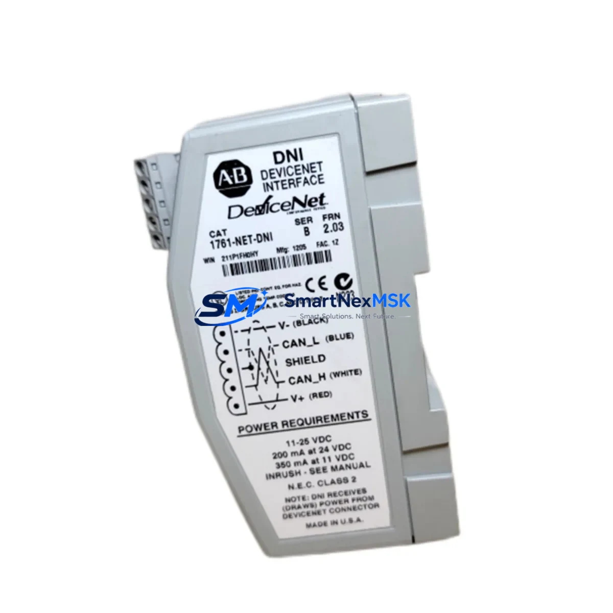
Allen-Bradley 1761-NET-DNI Retrofit-Ready DeviceNet Interface for MicroLogix Control Systems
The Allen-Bradley 1761-NET-DNI is a DeviceNet Interface Module engineered for seamless integration with MicroLogix 1000, MicroLogix 1100, MicroLogix 1200, and MicroLogix 1500 controllers, as well as legacy SLC 500 platforms. As original 1761-NET-DNI units reach end-of-life and spare inventory becomes increasingly scarce, this retrofit-ready replacement module provides a direct, drop-in solution for engineers managing aging DeviceNet networks in manufacturing, material handling, packaging, and process control environments.
Whether you are replacing a failed unit on an active production line, upgrading a control cabinet that still relies on DeviceNet topology, or migrating a legacy MicroLogix system toward a more maintainable architecture, the 1761-NET-DNI delivers the protocol bridge your network requires — without forcing a full controller replacement or reprogramming effort.
Upgrade Compatibility Table
| Parameter | Details |
|---|---|
| Compatible Controllers | MicroLogix 1000, 1100, 1200, 1500; SLC 500 series |
| Interface Connection | DIN rail mount; connects via MicroLogix communication port (RJ45 / RS-232 pass-through) |
| Network Protocol | DeviceNet (CAN-based, ISO 11898) |
| Baud Rates Supported | 125 kbps, 250 kbps, 500 kbps |
| Node Address Range | 0–63 (configurable via rotary switches) |
| Power Supply Requirement | 24 VDC from DeviceNet network bus |
| Replacement Compatibility | Direct drop-in for original Allen-Bradley 1761-NET-DNI (Series A/B) |
| Installation Requirement | No hardware modification; retains original terminal wiring and node address settings |
| Communication Compatibility | Compatible with RSNetWorx for DeviceNet; EDS file supported |
| Commissioning Notes | Verify node address, baud rate, and EDS registration before going live |
| Warranty | 12-Month Warranty — covers manufacturing defects and functional failures |
Retrofit Planning for Existing Automation Systems
A successful 1761-NET-DNI retrofit begins well before the module arrives on site. Engineers should audit the existing DeviceNet segment to confirm network topology, total node count, cable length, and termination resistor placement. In most MicroLogix-based control cabinets, the 1761-NET-DNI is mounted adjacent to the MicroLogix 1200 or MicroLogix 1500 controller and connected via the dedicated communication port. Before removal of the failed module, document the rotary switch positions for both the MAC ID and baud rate — these settings must be replicated exactly on the replacement unit to avoid node conflicts.
In systems where the MicroLogix controller communicates upstream to a 1747-SDN SLC 500 DeviceNet Scanner or a 1756-DNB ControlLogix DeviceNet Bridge, the 1761-NET-DNI acts as a slave node on the DeviceNet segment. Confirm that the scanner’s I/O mapping table still reflects the correct node address and data size for the 1761-NET-DNI after replacement. If the control system also includes a 1761-CBL-PM02 programming cable or a 1761-CBL-HM02 HMI cable for local configuration access, ensure these are disconnected before module swap to prevent communication faults during the changeover.
For cabinets that combine DeviceNet I/O with discrete wiring — such as 1769-IQ16 CompactLogix digital input modules or 1762-IQ8 MicroLogix expansion I/O — verify that the DeviceNet network power supply (typically a 1787-DNPS DeviceNet Power Supply or equivalent 24 VDC bus supply) is within specification before energizing the replacement module. Insufficient bus current is a common cause of intermittent communication faults after module replacement and is frequently overlooked during rapid changeovers.
If the retrofit is part of a broader migration from a MicroLogix platform toward a Micro820 or Micro850 controller with EtherNet/IP as the primary network, the 1761-NET-DNI can serve as a transitional bridge, keeping the existing DeviceNet field devices — such as PowerFlex 40 drives or ArmorBlock 1732D I/O modules — operational while the new controller infrastructure is commissioned in parallel. This phased approach significantly reduces the scope of a single cutover event and allows field device EDS files and I/O configurations to be validated before the legacy MicroLogix is decommissioned.
Panel builders and system integrators should also confirm HMI screen compatibility. PanelView 300 Micro or PanelView Plus terminals connected to the MicroLogix via DF1 or DH-485 are unaffected by the DeviceNet module swap, but any HMI screens that display DeviceNet network status diagnostics should be tested post-commissioning to confirm that network health indicators update correctly with the replacement module in service.
Downtime Control During System Migration
Minimizing unplanned downtime during a 1761-NET-DNI replacement requires a structured pre-swap checklist. Before taking the system offline, capture a full backup of the MicroLogix program using RSLogix 500 or Studio 5000 Logix Designer (if applicable to the broader system). Export the RSNetWorx for DeviceNet network configuration file so that node assignments, I/O sizes, and EDS registrations can be restored quickly if the network does not come up cleanly after the module swap.
During the physical swap, the DeviceNet trunk cable and drop cable connections at the module’s 5-pin open-style connector should be labeled before removal. The network termination resistors at both ends of the DeviceNet trunk must remain in place throughout the swap — removing them will cause reflections and communication errors on any nodes that remain powered during the changeover window. If a partial shutdown is possible, isolating only the DeviceNet segment while keeping the MicroLogix controller in program mode (rather than run mode) allows the rest of the control system to remain in a safe, known state.
After installing the replacement 1761-NET-DNI, power up the DeviceNet bus and observe the module status LEDs: the MS (Module Status) LED should display solid green, and the NS (Network Status) LED should display solid green once the scanner has established communication. A flashing red NS LED typically indicates a node address conflict or baud rate mismatch — both of which are resolved by re-checking the rotary switch settings against the original documentation. Once network health is confirmed in RSNetWorx, return the MicroLogix to run mode and verify that all DeviceNet I/O data is updating correctly in the controller’s data table before releasing the line back to production.
Retrofit Support FAQ
Q1: Is this a direct replacement for the original Allen-Bradley 1761-NET-DNI, and will it work without program changes?
Yes. This module is a direct drop-in replacement for the original 1761-NET-DNI (Series A and Series B). No changes to the MicroLogix ladder logic program are required, provided the MAC ID and baud rate rotary switches are set to match the original module’s configuration. The DeviceNet scanner’s I/O mapping table does not need to be modified.
Q2: What wiring checks should be performed before installing the replacement module?
Verify that the 5-pin DeviceNet connector wiring follows the standard color code: V+ (red), V− (black), CAN_H (white), CAN_L (blue), and Shield (bare/drain). Confirm that the network bus voltage at the connector is within the 11–25 VDC range specified for DeviceNet. Inspect the drop cable for damage, and ensure the trunk termination resistors (121 Ω) are present at both ends of the DeviceNet segment before powering up.
Q3: How is compatibility verified before the module is shipped?
Each unit undergoes functional testing prior to dispatch, including power-on self-test, LED status verification, and DeviceNet communication handshake validation. Units are shipped with an inspection report confirming test results. The 12-month warranty covers all manufacturing defects and functional failures identified after installation under normal operating conditions.
Q4: What is covered under the 12-month warranty, and what is the support process?
The 12-month warranty covers manufacturing defects, component failures, and communication faults attributable to the module itself. It does not cover damage caused by incorrect wiring, overvoltage, or physical mishandling. To initiate a warranty claim, contact our technical support team with the order number, a description of the fault symptom, and LED status observations. Replacement or repair is processed within 5–7 business days of fault confirmation.
© 2026 SMARTNEXMSK. All rights reserved.
Original Source: https://smartnexmsk.com
Contact: [email protected] | +86 18259474341



