
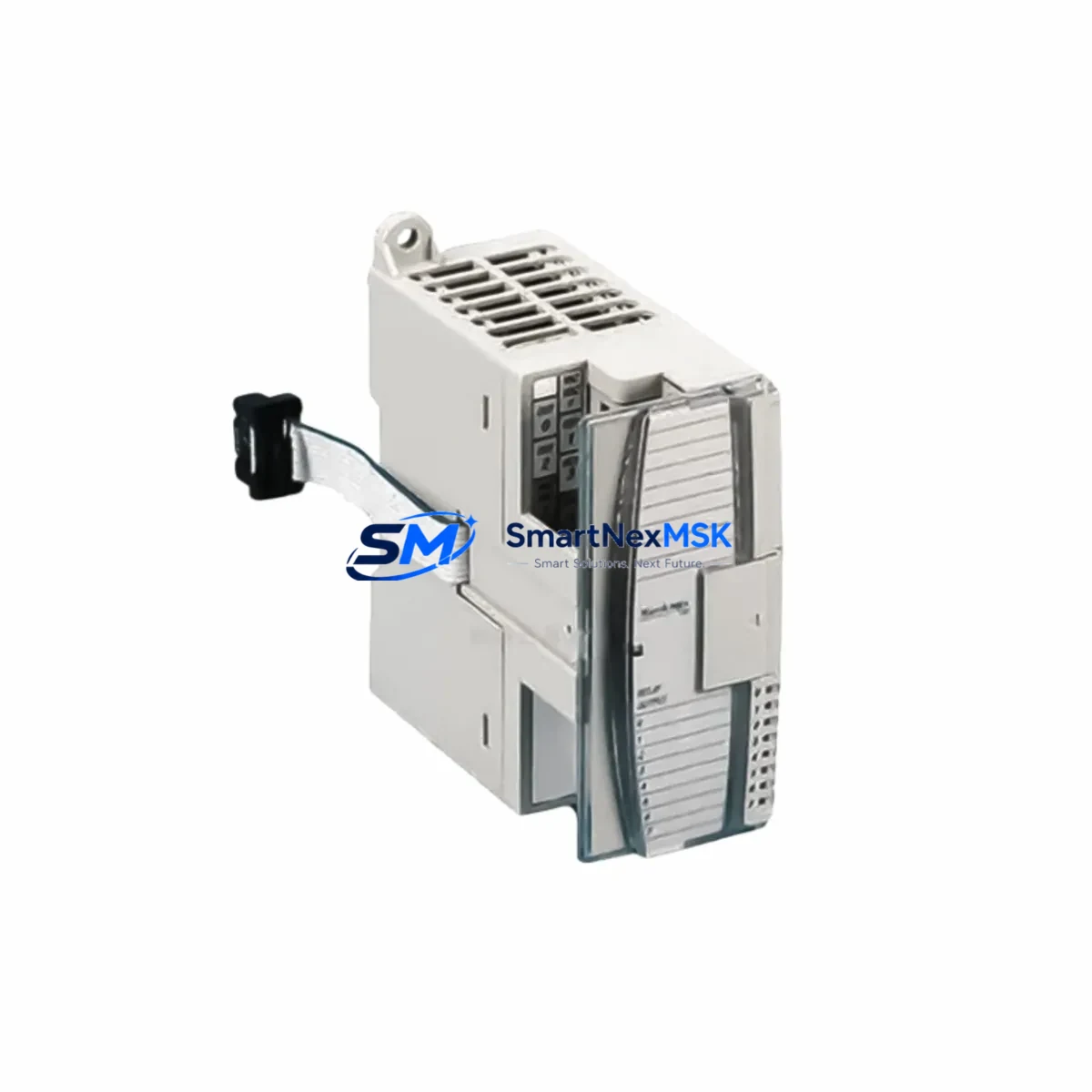
Allen-Bradley 1762-IF2OF2 Spare for MicroLogix Automation: Spare Replacement & Industrial Downtime Risk Control
The Allen-Bradley 1762-IF2OF2 is a combination analog input/output expansion module designed for MicroLogix 1200 and MicroLogix 1500 control systems. With 2 analog inputs and 2 analog outputs in a single compact module, it is a critical component in process control panels, machine automation lines, and legacy PLC-based systems across manufacturing, water treatment, HVAC, and energy sectors. When this module fails or degrades, the entire analog signal chain — including sensor feedback loops, valve positioning, and drive speed references — can be disrupted, causing unplanned downtime and production loss.
Sourced as an original Allen-Bradley spare, this 1762-IF2OF2 unit is tested prior to shipment, packaged for safe transport, and backed by a 12-month warranty. It is available for immediate dispatch to support emergency replacement and planned maintenance programs alike.
Spare Maintenance Table
| Parameter | Specification |
|---|---|
| Part Number | 1762-IF2OF2 |
| Brand | Allen-Bradley (Rockwell Automation) |
| Series | MicroLogix 1762 Expansion |
| Compatible Controllers | MicroLogix 1200 (1762-Lxx), MicroLogix 1500 (1764-Lxx) |
| Analog Inputs | 2 channels — 0–10 VDC / 4–20 mA (software selectable) |
| Analog Outputs | 2 channels — 0–10 VDC / 4–20 mA (software selectable) |
| Resolution | 12-bit (inputs & outputs) |
| Input Impedance | ≥ 10 MΩ (voltage mode); 250 Ω (current mode) |
| Supply Voltage | Powered via MicroLogix bus (no external supply required) |
| Operating Temperature | 0 °C to 60 °C |
| Mounting | DIN rail or panel mount via MicroLogix expansion bus connector |
| Certifications | UL, CE, cUL |
| Origin | USA (Allen-Bradley / Rockwell Automation) |
| Condition | Original spare — tested before shipment |
| Warranty | 12 months from date of delivery |
| Maintenance Recommendation | Inspect wiring terminals and analog signal calibration every 12 months; replace if drift exceeds ±1% of full scale |
Maintenance Planning for Continuous Operation
When a MicroLogix system requires replacement of the 1762-IF2OF2 analog I/O module, maintenance engineers should treat the event as an opportunity to inspect the broader control cabinet and signal chain. Analog module failures are rarely isolated — they are often preceded or accompanied by degradation in adjacent components.
Begin by verifying the integrity of the 1762-L24AWA or 1762-L40AWA MicroLogix 1200 CPU base unit. Check the expansion bus connector for corrosion or mechanical damage, as a poor bus connection can cause intermittent analog faults that mimic module failure. Inspect the 1762-OW16 relay output module and 1762-IQ16 digital input module in the same rack — shared bus faults can affect multiple modules simultaneously.
Review the 24 VDC power supply feeding the panel. Voltage ripple or sag under load is a common root cause of analog signal instability. If the panel uses a 1606-XLP power supply or equivalent, verify output voltage under full load conditions. A degraded power supply can cause the 1762-IF2OF2 to report erratic analog values without triggering a hard fault.
Inspect all analog signal wiring connected to the module’s input and output terminals. Shielded twisted-pair cables should be grounded at one end only; improper grounding introduces noise that corrupts 4–20 mA signals. Check terminal blocks — particularly Phoenix Contact or Weidmüller screw-type terminal strips — for loose connections, oxidation, or thermal discoloration indicating past overload events.
If the system includes signal isolators or loop-powered transmitters on the analog input channels, verify isolator output levels and confirm that transmitter loop resistance is within the module’s specified range. A failing 4–20 mA signal isolator can cause the 1762-IF2OF2 to read a fixed or saturated value, which is often misdiagnosed as module failure.
For systems with PanelView 300 or PanelView 550 HMI terminals communicating with the MicroLogix controller via DH-485, inspect the 1761-NET-AIC Advanced Interface Converter and associated RS-232/DH-485 cabling. Communication faults at the HMI level can mask analog I/O errors in the controller’s fault log. Also check any 1761-CBL-PM02 programming cables used for periodic firmware updates or diagnostic access.
Finally, review the fuse protection on analog output circuits. Unprotected output channels driving inductive loads (such as proportional valves or variable frequency drives) are susceptible to transient damage. Installing appropriately rated fuses or surge protection modules on output wiring extends the service life of the 1762-IF2OF2 and reduces the frequency of unplanned replacements.
Site Replacement Workflow
Step 1 — Identify and document: Before removing the existing module, record the current analog I/O configuration using RSLogix 500 or Studio 5000 Logix Designer. Export the program file and note all channel configurations (input range, output range, filter settings) to ensure the replacement module is configured identically.
Step 2 — Safe isolation: Place the MicroLogix controller in Program mode via the keyswitch or software. De-energize the panel following your site’s lockout/tagout (LOTO) procedure. Disconnect all analog signal wiring from the 1762-IF2OF2 terminals, labeling each wire before removal.
Step 3 — Module removal and inspection: Disconnect the expansion bus connector and remove the module from the DIN rail. Inspect the bus connector pins on both the removed module and the adjacent module or CPU for damage or contamination. Clean with isopropyl alcohol if necessary.
Step 4 — Install replacement: Mount the new 1762-IF2OF2 on the DIN rail and reconnect the expansion bus. Reconnect all analog signal wiring per your documented labels. Verify terminal torque to manufacturer specification (typically 0.5–0.6 N·m for M3 screws).
Step 5 — Configuration and verification: Restore power and download the saved program to the controller. Verify that the replacement module is recognized by the CPU (check I/O tree in RSLogix 500). Apply a known reference signal to each analog input channel and confirm the controller reads the expected value. Drive each analog output to a known setpoint and verify the field device responds correctly.
Step 6 — Return to service: Place the controller back in Run mode. Monitor analog values for the first 30 minutes of operation to confirm stable, noise-free signals. Update your maintenance log and spare parts inventory accordingly.
Spare Parts Support FAQ
Q1: Is this 1762-IF2OF2 an original Allen-Bradley part or a third-party replacement?
This is an original Allen-Bradley (Rockwell Automation) spare part. It is not a clone, aftermarket reproduction, or refurbished unit. Each unit is sourced through verified supply channels and undergoes functional testing before shipment to confirm analog I/O performance within factory specifications.
Q2: What is the recommended spare parts inventory strategy for MicroLogix analog modules?
For production-critical systems, we recommend maintaining at least one 1762-IF2OF2 on-site as a cold spare. Systems with multiple analog expansion modules or those operating in harsh environments (high vibration, temperature cycling, or chemical exposure) should consider a 1:4 spare ratio. Given that MicroLogix 1200 and 1500 are mature platforms, sourcing spare modules proactively is advisable as market availability may tighten over time.
Q3: How is compatibility verified before shipment?
Compatibility is verified against the module’s catalog number, firmware revision, and hardware revision markings. For orders where the customer provides the existing module’s revision label or controller firmware version, our technical team cross-references Rockwell Automation’s compatibility matrices to confirm the replacement is a direct fit. If any compatibility uncertainty exists, we will contact you before shipment.
Q4: What does the 12-month warranty cover, and what is the return process?
The 12-month warranty covers manufacturing defects and functional failures under normal operating conditions. It does not cover damage caused by incorrect installation, overvoltage, reverse polarity, or physical impact. To initiate a warranty claim, contact our sales team with your order number and a description of the fault. We will arrange return shipping and provide a replacement or full refund upon inspection confirmation.
© 2026 SMARTNEXMSK. All rights reserved.
Original Source: https://smartnexmsk.com
Contact: [email protected] | +86 18259474341



